Download
1 / 21
210 likes | 228 Vues
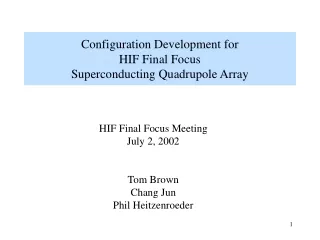
Configuration Development for HIF Final Focus Superconducting Quadrupole Array. HIF Final Focus Meeting July 2, 2002 Tom Brown Chang Jun Phil Heitzenroeder. Interface Issues. Thermal 4 K magnets must be insulated from 400 0 C Flinabe in a few mm of space. Vacuum

E N D
Configuration Development for HIF Final FocusSuperconducting Quadrupole Array HIF Final Focus Meeting July 2, 2002 Tom Brown Chang Jun Phil Heitzenroeder
Interface Issues • Thermal • 4 K magnets must be insulated from 4000 C Flinabe in a few mm of space. • Vacuum • 10-6 target chamber needs to be isolated from 10-9 beam lines. • Debris from target must be kept out of beam lines. • Electromagnetic Loads • Forces between quadrupole magnets must be reacted by strutures between the magnets. • Adequate preload on the magnets must be provided to avoid quenching, • Radiation • Magnets must be shielded for 30 yr. life. • Nuclear heating of the superconducting magnets must be as low as possible. • Alignment • Beam alignment must be maintained within TBD dimensions. • Maintenance & Assembly • Array should be capable of tolerating the loss of a few beam lines (symmetric side to side). • Goal: to be able to replace failed beam lines in <6 mos. • Array assembly must be practical from the field construction point of view. • Utility Feeds • Cryogenic feed lines, power lines, instrumentation lines, Flinabe lines from all of the 104 beam lines must all be accommodated.
Preliminary Concept • 52 Beam Lines / side • Focusing magnets utilize Nb3Sn superconductor. Targetchamber Focusing magnet
Chamber / Focusing Magnet Interface Detail Vacuum boundary
Support Tube / Vacuum Concept Vacuum Chamber Alignment Tubes
Configuration based on the Shell magnet arrangement. Shell magnet concept Support tube and guide Local detail
Beam geometry used in model Final focus quadrupoles Target Dipole
Magnet preload compression jacket Nb3Sn Magnets Thermal & Radiation Shielding Exploded View Inner vacuum pipe Quadrupole Details Magnet Assembly Ground wall electrical insulation
Last Magnet Build Dimensions Proposed alternate build Jeff Latkowski shield build
Magnets Installed in Guide Tubes Detail The “nose” is the difficult area. There is insufficient space for the guide tubes. The dipoles here will be supported by the vacuum pipes. Bulk shielding is a problem!
Simplified Configuration Lattice space: 60 by 60cm
Force Direction & Magnitude 0.707q/a a 0.28q/a 0.07q/a q=2*107 a=0.6m
Edge Magnets • Note uncompensated edge magnets have 10 times the force on them as inner magnets! • An option suggested by MIT is to provide a set of “edge magnets” surrounding the quadrupoles. Advantages: • Force on focusing magnets would be reduced and therefore alignment will be easier to maintain. • Structures between focusing magnets can be greatly reduced in size. • The “active” focusing magnets will all be the same and will operate at the same current.
Electromagnetic Analysis of Shell Type Magnet Design July 2002 cjun@pppl.gov One conductor has 1*10cm section. 20cm 40cm IFE: Conductors section at the End stage of compression 1-6
July 2002 cjun@pppl.gov C3 C2 C1 ZC3 ZC2 B4 B3 B2 ZC1 ZB3 ZB2 B1 ZB1 A3 A2 ZA3 ZA2 A1 ZA1 IFE: Conductors section of first quarter 2-6
July 2002 cjun@pppl.gov IFE: Conductors section & magnetic flux lines 3-6
July 2002 cjun@pppl.gov IFE: Conductors section & magnetic flux lines in first quarter 4-6
July 2002 cjun@pppl.gov IFE: Conductors section & magnetic flux lines (magnified) 5-6
July 2002 cjun@pppl.gov IFE: magnetic forces at conductors (ANSYS, current is 1MA) . (see 2-6 for the conductors position with names) 6-6
Conclusion • The design shown is only a “first cut”. • Basic philosophy of this design is to allow each focusing beam array to be individually removed. • The inner magnet triplets are all contained in a common vacuum chamber, but there are issues. • This design locates radiation shielding in the vortex tube region and around the sides of vacuum housing. Is this adequate? • There is insufficient space in first focusing magnet region. This area is almost totally occupied by the focusing magnets, leaving no room for the guide tubes or shielding. • All magnets must transfer electromagnetic loads through the superconducting thermal insulation. Concepts for doing this need to be developed. • Bulk radiation shielding will be located in the vacuum housing. Outgassing may be a problem. • Maintainability issues need to be more fully understood from the points of view of component activation and personnel access. • Shell type magnet design is used since this easily allows “compression collars” to surround the coil to inhibit coil motion. The shell design lends itself to the conical array of magnets. • Initial electromagnetic analyses have been performed for both the “block” and “shell” magnet configurations. • Forces on the outer coils are large, but the addition of “edge coils” can significantly reduce them.