Download
1 / 39
680 likes | 2.02k Vues
7.4 SHEAR FLOW IN BUILT-UP MEMBERS. Occasionally, in engineering practice, members are “built-up” from several composite parts in order to achieve a greater resistance to loads, some examples are shown.

E N D
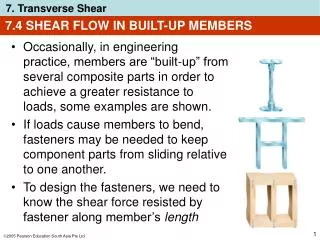
7.4 SHEAR FLOW IN BUILT-UP MEMBERS • Occasionally, in engineering practice, members are “built-up” from several composite parts in order to achieve a greater resistance to loads, some examples are shown. • If loads cause members to bend, fasteners may be needed to keep component parts from sliding relative to one another. • To design the fasteners, we need to know the shear force resisted by fastener along member’s length
7.4 SHEAR FLOW IN BUILT-UP MEMBERS • This loading, measured as a force per unit length, is referred to as the shear flow q. • Magnitude of shear flow along any longitudinal section of a beam can be obtained using similar development method for finding the shear stress in the beam
q = VQ/I 7.4 SHEAR FLOW IN BUILT-UP MEMBERS • Thus shear flow is Equation 7-6 q = shear flow, measured as a force per unit length along the beam V = internal resultant shear force, determined from method of sections and equations of equilibrium I = moment of inertia of entire x-sectional area computed about the neutral axis Q =∫A’ ydA’ = y’A’, where A’is the x-sectional area of segment connected to beam at juncture where shear flow is to be calculated, andy’is distance from neutral axis to centroid ofA’
7.4 SHEAR FLOW IN BUILT-UP MEMBERS • Note that the fasteners in (a) and (b) supports the calculated value of q • And in (c) each fastener supports q/2 • In (d) each fastener supports q/3
7.4 SHEAR FLOW IN BUILT-UP MEMBERS IMPORTANT • Shear flow is a measure of force per unit length along a longitudinal axis of a beam. • This value is found from the shear formula and is used to determine the shear force developed in fasteners and glue that holds the various segments of a beam together
EXAMPLE 7.4 Beam below is constructed from 4 boards glued together. It is subjected to a shear of V = 850 kN. Determine the shear flow at B and C that must be resisted by the glue.
y A y y = = ... = 0.1968 m EXAMPLE 7.4 (SOLN) Section properties Neutral axis (centroid) is located from bottom of the beam. Working in units of meters, we have Moment of inertia about neutral axis is I = ... = 87.52(10-6) m4
QC = y’C A’C = ... = 0.01025(10-3) m3 EXAMPLE 7.4 (SOLN) Section properties Since the glue at B and B’ holds the top board to the beam, we have QB = y’B A’B = [0.305 m 0.1968 m](0.250 m)(0.01 m) QB = 0.270(10-3) m3 Likewise, glue at C and C’ holds inner board to beam, so
EXAMPLE 7.4 (SOLN) Shear flow For B and B’, we have q’B = VQB /I = [850 kN(0.270(10-3) m3]/87.52(10-6) m4 q’B = 2.62 MN/m Similarly, for C and C’, q’C = VQC /I = [850 kN(0.0125(10-3) m3]/87.52(10-6) m4 q’C = 0.0995 MN/m
EXAMPLE 7.4 (SOLN) Shear flow Since two seams are used to secure each board, the glue per meter length of beam at each seam must be strong enough to resist one-half of each calculated value of q’. Thus qB = 1.31 MN/m qC = 0.0498 MN/m
7.5 SHEAR FLOW IN THIN-WALLED MEMBERS • We can use shear-flow equation q = VQ/I to find the shear-flow distribution throughout a member’s x-sectional area. • We assume that the member has thin walls, i.e., wall thickness is small compared with height or width of member
7.5 SHEAR FLOW IN THIN-WALLED MEMBERS • Because flange wall is thin, shear stress will not vary much over the thickness of section, and we assume it to be constant. Hence, q = t Equation 7-7 • We will neglect the vertical transverse component of shear flow because it is approx. zero throughout thickness of element
Vt d 2I q = (b/2 x) 7.5 SHEAR FLOW IN THIN-WALLED MEMBERS • To determine distribution of shear flow along top right flange of beam, shear flow is Equation 7-8
Vt I db 2 [ ] q = +0.5(d2/4 y2) 7.5 SHEAR FLOW IN THIN-WALLED MEMBERS • Similarly, for the web of the beam, shear flow is Equation 7-9
7.5 SHEAR FLOW IN THIN-WALLED MEMBERS • Value of q changes over the x-section, since Q will be different for each area segment A’ • q will vary linearly along segments (flanges) that are perpendicular to direction of V, and parabolically along segments (web) that are inclined or parallel to V • q will always act parallel to the walls of the member, since section on which q is calculated is taken perpendicular to the walls
7.5 SHEAR FLOW IN THIN-WALLED MEMBERS • Directional sense of q is such that shear appears to “flow” through the x-section, inward at beam’s top flange, “combining” and then “flowing” downward through the web, and then separating and “flowing” outward at the bottom flange
7.5 SHEAR FLOW IN THIN-WALLED MEMBERS IMPORTANT • If a member is made from segments having thin walls, only the shear flow parallel to the walls of member is important • Shear flow varies linearly along segments that are perpendicular to direction of shear V • Shear flow varies parabolically along segments that are inclined or parallel to direction of shear V • On x-section, shear “flows” along segments so that it contributes to shear V yet satisfies horizontal and vertical force equilibrium
EXAMPLE 7.7 Thin-walled box beam shown is subjected to shear of 10 kN. Determine the variation of shear flow throughout the x-section.
EXAMPLE 7.7 (SOLN) By symmetry, neutral axis passes through center of x-section. Thus moment of inertia is I = 1/12(6 cm)(8 cm)3 1/12(4 cm)(6 cm)3 = 184 cm4 Only shear flows at pts B, C and D needs to be determined. For pt B, area A’≈ 0 since it can be thought of located entirely at pt B. Alternatively, A’ can also represent the entire x-sectional area, in which case QB = y’A’ = 0 since y’= 0.
EXAMPLE 7.7 (SOLN) Because QB = 0, then qB = 0 For pt C, area A’ is shown dark-shaded. Here mean dimensions are used since pt C is on centerline of each segment. We have QC = y’A’ = (3.5 cm)(5 cm)(1 cm) = 17.5 cm3 qC = VQC/I = ... = 95.1 N/mm
EXAMPLE 7.7 (SOLN) Shear flow at D is computed using the three dark-shaded rectangles shown. We have QD = y’A’ = ... = 30 cm3 qC = VQD/I = ... = 163 N/mm
EXAMPLE 7.7 (SOLN) Using these results, and symmetry of x-section, shear-flow distribution is plotted as shown. Distribution is linear along horizontal segments (perpendicular to V) and parabolic along vertical segments (parallel to V)
*7.6 SHEAR CENTER • Previously, we assumed that internal shear V was applied along a principal centroidal axis of inertia that also represents the axis of symmetry for the x-section • Here, we investigate the effect of applying the shear along a principal centroidal axis that is not an axis of symmetry • When a force P is applied to a channel section along the once vertical unsymmetrical axis that passes through the centroid C of the x-sectional area, the channel bends downwards and also twist clockwise
e = (Ff d)/P *7.6 SHEAR CENTER • When the shear-flow distribution is integrated over the flange and web areas, a resultant force of Ff in each flange and a force of V=P in the web is created • If we sum the moments of these forces about pt A, the couple (or torque) created by the flange forces causes the member to twist • To prevent the twisting, we need to apply P at a pt O located a distance e from the web of the channel, thus MA = Ff d = Pe
*7.6 SHEAR CENTER • Express Ff is expressed in terms of P (= V) and dimensions of flanges and web to reduce e as a function of its x-sectional geometry • We name the pt O as the shear center or flexural center • When P is applied at the shear center, beam will bend without twisting • Note that shear center will always lie on an axis of symmetry of a member’s x-sectional area
*7.6 SHEAR CENTER IMPORTANT • Shear center is the pt through which a force can be applied which will cause a beam to bend and yet not twist • Shear center will always lie on an axis of symmetry of the x-section • Location of the shear center is only a function of the geometry of the x-section and does not depend upon the applied loading
*7.6 SHEAR CENTER Procedure for analysis Shear-flow resultants • Magnitudes of force resultants that create a moment about pt A must be calculated • For each segment, determine the shear flow q at an arbitrary pt on segment and then integrate q along the segment’s length • Note that V will create a linear variation of shear flow in segments that are perpendicular to V and a parabolic variation of shear flow in segments that are parallel or inclined to V
*7.6 SHEAR CENTER Procedure for analysis Shear-flow resultants • Determine the direction of shear flow through the various segments of the x-section • Sketch the force resultants on each segment of the x-section • Since shear center determined by taking the moments of these force resultants about a pt (A), choose this pt at a location that eliminates the moments of as many as force resultants as possible
*7.6 SHEAR CENTER Procedure for analysis Shear center • Sum the moments of the shear-flow resultants about pt A and set this moment equal to moment of V about pt A • Solve this equation and determine the moment-arm distance e, which locates the line of action of V from pt A • If axis of symmetry for x-section exists, shear center lies at the pt where this axis intersects line of action of V
*7.6 SHEAR CENTER Procedure for analysis Shear center • If no axes of symmetry exists, rotate the x-section by 90o and repeat the process to obtain another line of action for V • Shear center then lies at the pt of intersection of the two 90o lines
EXAMPLE 7.8 Determine the location of the shear center for the thin-walled channel section having the dimensions as shown.
EXAMPLE 7.8 (SOLN) Shear-flow resultants Vertical downward shear V applied to section causes shear to flow through the flanges and web as shown. This causes force resultants Ffand V in the flanges and web.
VQ I V(b – x) h[(h/6) + b] q = = EXAMPLE 7.8 (SOLN) Shear-flow resultants X-sectional area than divided into 3 component rectangles: a web and 2 flanges. Assume each component to be thin, then moment of inertia about the neutral axis is I = (1/12)th3 + 2[bt(0.5h)2] = (0.5th2)[(h/6) + b] Thus, q at the arbitrary position x is
Vb2 2h[(h/6) + b] b Ff= ∫0q dx = … = EXAMPLE 7.8 (SOLN) Shear-flow resultants Hence, The same result can be determined by first finding (qmax)f, then determining triangular area 0.5b(qmax)f = Ff
b2 [(h/3) +2b] e = EXAMPLE 7.8 (SOLN) Shear center Summing moments about pt A, we require Ve = Ff h … As stated previously, e depends only on the geometry of the x-section.
CHAPTER REVIEW • Transverse shear stress in beams is determined indirectly by using the flexure formula and the relationship between moment and shear (V = dM/dx). This result in the shear formula = VQ/It. • In particular, the value for Q is the moment of the area A’ about the neutral axis. This area is the portion of the x-sectional area that is “held on” to the beam above the thickness t where is to be determined
CHAPTER REVIEW • If the beam has a rectangular x-section, then the shear-stress distribution will be parabolic, obtaining a maximum value at the neutral axis • Fasteners, glues, or welds are used to connect the composite parts of a “built-up” section. The strength of these fasteners is determined from the shear flow, or force per unit length, that must be carried by the beam; q = VQ/I • If the beam has a thin-walled x-section then the shear flow throughout the x-section can be determined by using q = VQ/I
CHAPTER REVIEW • The shear flow varies linearly along horizontal segments and parabolically along inclined or vertical segments • Provided the shear stress distribution in each element of a thin-walled section is known, then, using a balance of moments, the location of the shear center for the x-section can be determined. • When a load is applied to the member through this pt, the member will bend, and not twist