Shear Flow
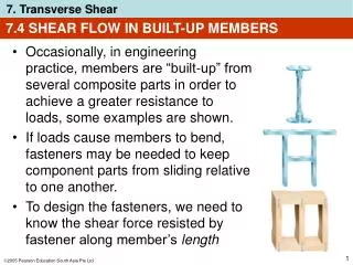
Shear Flow. Beams Subjected to Bending Loads. So why did these Beams split down Their length?. Maybe they Just Dried Out – They are all Wood. Of course these aren’t wood. Maybe We Can Find Answers in Our Shear and Moment Diagrams. Hear is a shear and moment Diagram, but I don’t


Shear Flow
E N D
Presentation Transcript
Beams Subjected to Bending Loads So why did these Beams split down Their length?
Maybe they Just Dried Out – They are all Wood Of course these aren’t wood.
Maybe We Can Find Answers in Our Shear and Moment Diagrams Hear is a shear and moment Diagram, but I don’t See anything horizontal.
Consider a Beam in Bending We all know the top of the beam compresses and the bottom goes into tension And there is a neutral axis in the middle yadayadayada Not Expected . Expected
Lets Grab a Little Piece of that Beam Where Shear is Constant We have nice balancing vertical Equilibrium But why doesn’t it spin? Could it be that we have a mystery force?
What Else Could be Happening as a Beam Bends Mystery Solved
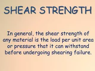
So What Kinds of Numbers are We Talking? We know we can’t Have shear at the Air interface It can’t be even
Ok – So What is Q Lets consider a horizontal plane On a beam so distance y1 away From the neutral axis
And What About I? The moment of inertia of the beam
Lets Do Something With It Obviously the neutral plane is Right through the middle Lets go get the Shear flow on The edge of the Boards!
Now for I Middle board part is Easy. If this were a steel I beam We could just look up I. Unfortunately we are going To have to calculate it. Of course we’re still missing the contribution Of the boards on the ends.
For Our End Boards we Will be rescued by the Parallel Axis Theorem
Getting the Shear Flow Note that shear flow is shear force per Unit of beam length. In our case we are interested in what is trying to shear our nails in two if they are Placed every 25 mm
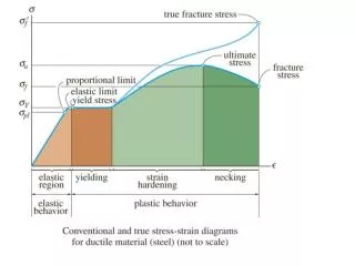
Nice Spot Check of Shear Stress, but What Does the Stress Profile Look Like? Note this means the peak stress is 1.5 * Average Shear Stress
Then there are typical Steel Beams So that’s why the Web crumpled up.
Designing a Beam This could Go wrong! The beam Could split In axial Tension.
Lets Make Sure That Doesn’t Happen We will use our shear and moment diagrams To find the maximum bending moment Then we will zero in on the required Section modulus
Obviously the Next Thing I Need Is Section Modulus as a Function of Beam Depth Remember – Section Modulus Is Moment of Inertia over c Where c is the distance from The neutral axis to the edge of The beam.
Plug it in Plug it in From Our Moment Diagram Just worked out by our Substitution Given in the problem Solving the equation for d
Looks Like We Need a 4 X 10 for Our Beam After all – could anything else go wrong
Yes – We Better Check the Shear Flow We know the maximum sheer will be at the center Of the beam T allowable is 120 psi
Plug and Chug We didn’t watch the sheer flow And it nearly bit us in the _ _ _ _ Yipes! We were Going to use a 4 X 10 We need a 4 X 12 for this.
Lets Use Mohr’s Circle to Take a Look at the Beam Center An Element At the Beam Center This element is subject to Strong shear forces, but What about axial force? (assume its on the neutral Axis)
Pure Shear Our worst Case is near The beam edges If we assume we use a 4 X 12
Now to Mohr’s Circle Plot the clockwise shear 114.29 τ σ Since we have pure Shear there is no Tension or compression On these faces. At 90 degrees to That we find a Counter clockwise shear -114.29
Since We Have Pure Shear We Have No Tension or Compression? Right? What is this? What angle Is that on? Is it possible that shear flow could buckle A ductile material in compression on a 45 Degree diagonal plane?