SHEAR STRENGTH
SHEAR STRENGTH. In general, the shear strength of any material is the load per unit area or pressure that it can withstand before undergoing shearing failure. Shearing Pins can be used to fasten together two steel plates:. With high enough plate forces in opposite directions….

SHEAR STRENGTH
E N D
Presentation Transcript
SHEAR STRENGTH In general, the shear strength of any material is the load per unit area or pressure that it can withstand before undergoing shearing failure.
Shearing Pins can be used to fasten together two steel plates: With high enough plate forces in opposite directions… How do these fail? When you hear “Shear Failure” you probably think of Shearing Pins or Bolts. Each pin has sheared into two pieces.
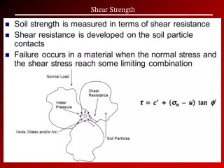
The failure plane for metals will be parallel to the external shear forces. If the shear force causes failure, then the shear stress that results, τf is the shear strength of the material. The internal shear stress, τis simply the shear force, T acting on the failure plane divided by the area, A of the failure plane: So shear forces are those that tend to cause shear failure. T Area, A
Since the external force is acting parallel to the failure plane, the internal strength of the material is thought of as its internal friction, F. This is the material’s reaction to the external shear force, T. The Shear Force that acts on the failure plane is resisted by the strength of the material. F T
The tangent of the friction angle, is the ratio of F to W which is also known as the coefficient of friction. and thereby cause the object to move. Vector addition gives the resultant vector, R which acts at an angle of WRT the normal to the plane. that must be applied to an object of known weight, W The object’s weight vector, W acts normal to the failure plane. Friction problems in mechanics determine the external force, T R W W F to overcome the friction force, F on the plane where the object rests T
Consider and element of soil within a large soil mass: If the soil is loaded (yet sober): LOAD Soil Surface SHEAR STRENGTH IN SOILS Soil Element The loading of a material that undergoes shear failure is not always parallel to the failure plane. Soil Mass Bedrock
LOAD σ1 The load transmits stress to the element by inter-particle contacts. This is the major principal stress distribution, designated σ1 due to the load. For visual simplicity we replace the distributed load with an equivalent point load.
σ1 σ2 σ3 σ3 σ2 σ1 The soil below the element will react with a stress of equal magnitude but directed upwards so it too is designated σ1. The element squeezed vertically will tend to bulge horizontally to which the soil reacts with confining pressures σ2and σ3 in the other principal directions. Since we assume the soil is isotropic, the confining lateral pressure will be the same in all directions and so σ2 =σ3 allowing us to view it in 2 dimensions.
For this to happen, a failure plane develops within the soil. The friction force on this failure plane is overcome by the external forces and viola: Soil undergoes shear failurewhen one portion moves relative to the rest. SHEAR FAILURE! σ1 2-D But what has this got to do with SHEAR STRENGTH? Θ σ1
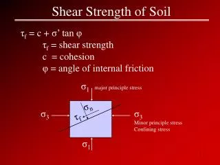
The angle of internal friction, characterizes the shear strength of the soil and is one of its shear strength parameters. There are 3 basic laboratory tests that can be performed on soil samples to evaluate the shear strength parameters: • 1. Direct Shear Test • 2. Triaxial Compression Test • 3. Unconfined Compression Test σf Rf The Shear Stress at failure, τf, is the pressure required to overcome the friction on the surface of the failure plane (a.k.a. Shear Strength). τf Θ
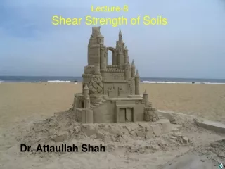
DIRECT SHEAR TEST Can be performed on all types of soil, moist or dry. Measures shear stress at failure on failure plane for various normal stresses. Failure plane is controlled (parallel to direction of applied load).
DIRECT SHEAR TEST The horizontal force is increased until the sample shears in two: This forces failure to occur on a horizontal plane between the top and base: Then the top and base are pushed in opposite directions A normal (90 to the horizontal) load is applied to the soil. The prepared soil sample is placed in the box. A shear box has three parts: and a normal load piston a base a top extension The procedure is repeated two more times using successively heavier normal loads.
DIRECT SHEAR TEST In the CV504 labs, the inside dimensions of the shear box are 60 mm by 60 mm. This means the failure plane has an area of 3600 mm2. The shear force at failure (maximum) and normal load, both in Newtons are divided by this plane area to find the shear stress at failure and the normal stress in MPa. The shear force required to shear the sample increases in proportion to the normal load. The shear strength of the soil therefore is not constant but changes with the confining pressure. For this reason, the soil’s shear strength is characterized by shear strength parameters: (c,).
DIRECT SHEAR TEST The τaxis intercept is the apparent cohesion, c of the soil. Fitting a best fit line through these points: The equation of Coulomb’s failure envelope: τf= c + σntan . Plotting the shear stress versus normal stress: The slope angle of this line is the angle of internal friction, of the soil. we have an estimate of Coulomb’s failure envelope First Test Second Test Third Test τf τf Shear Stress, τ(kPa) τf c Normal Stress, σn(kPa)
TRIAXIAL COMPRESSION TEST Can be performed on all types of soil, moist or dry and can consolidate sample to in situ conditions by tracking pore water pressures. Measures vertical stress applied to soil sample and confining pressure. Shear stress on failure plane must be calculated from principal stresses.
TRIAXIAL COMPRESSION TEST Cylindrical specimens are prepared from sampled soil. Specimens are weighed and dimensions measured first. Preparation varies with material properties (clay vs sand vs cohesive granular). The specimen is mounted between 2 platens and then inserted into a latex sleeve. The specimen is then placed in a plexiglas chamber. diameter length
TRIAXIAL COMPRESSION TEST Then the chamber is placed on the base and locked into place. For a drained test the drain valve is opened and pore water collected. Once the cell is filled with water, the air release valve is closed and the cell pressure is increased to the desired value for the test. For an undrained test, the drain valve is closed. Water is forced into the cell with the supply valve open as well as the air release valve. The assembly is then mounted on the compression testing machine. The specimen is mounted on the pedestal of the chamber base as shown. loading ram air release valve plexiglas chamber loading cap water supply for cell (confining) pressure latex sleeve drainage or pore water pressure measurement specimen porous disc pedestal
TRIAXIAL COMPRESSION TEST Enter Christian Otto Mohr: The goal is to simulate the stresses confining the specimen in the ground. The Major Principal Stress, σ1, is the combination of the deviator stress and cell pressure: But how can we find τf and σf from σ1 and σ3 ? The effect of the cell pressure on the specimen is illustrated below: Then a vertical axial load is applied to the loading ram creating compressive stresses or the deviator stress ∆σ : The cell pressure, σ3, is also known as the Minor Principal Stress. ∆σ σ3 σ3 σ3 ∆σ Plan View of Specimen Side View of Specimen Source: “commons.wikimedia.org”
TRIAXIAL COMPRESSION TEST Herr Mohr was born in Germany on 1835-10-08 and was a renowned Civil Engineer and professor until his death on 1918-10-02. for any material, the internal shear and normal stresses acting on ANY plane within the material, In other words, he discovered MOHR’S CIRCLE. While contemplating the symmetry of his name, Otto started tinkering with the properties of the circle when he discovered that... caused by external stresses or loads can be determined using a trigonometric transformation of the external stresses.
TRIAXIAL COMPRESSION TEST If you plot σ1 and σ3 on the σn axis Ultimately, the test ends when shear failure occurs and the circle has become tangent to the failure envelope. During the test, this circle starts as one point at σ3 and then grows to the right as axial stress, ∆σ increases but σ3 remains constant. then fit one circle through these points The point of tangency of the circle and failure envelope defines the shear strength, τf and normal stress, σf. then you’ve got a Mohr’s circle! Remember the plot of Shear Stress versus Normal Stress? Shear Stress, τ (kPa) τf c σ1 σ1 σ3 σf ∆σ ∆σ σ1 ∆σ Normal Stress, σn(kPa)
TRIAXIAL COMPRESSION TEST If one line cannot be drawn tangent to all three circles, a best fit is made as long as one circle is not out to lunch compared to the others. But how can you be sure one of them isn’t bogus? As with most lab measurements, the ideal (one line tangent to all three circles) is difficult to achieve. Geometrically, you need at least two circles in order to define a line tangent to both. This means that you need to perform the test at least twice on the same material but at different cell pressures. A third test at yet another cell pressure would help to confirm the validity of the failure envelope. But how do we find the failure envelope from a triaxial compression test? Shear Stress, τ (kPa) c Normal Stress, σn(kPa)
TRIAXIAL COMPRESSION TEST Instead of doing this graphically, we can use trigonometry to find equations for τf and σf using the angle of the failure plane, Θ and the values of σ1 and σ3 Remember the deviator stress, ∆σ = σ1 - σ3, which is the diameter of the Mohr’s Circle. The Centre of the Mohr’s Circle, C is then: then for each test, the shear strength, τf and normal stress, σf can be found. So the radius of the Mohr’s Circle, R is half the diameter or: Once we have the shear strength parameters, and c defining the failure envelope, Shear Stress, τ (kPa) specimen Θ failure plane R c C R R Θ σ3 σ1 Normal Stress, σn(kPa)
TRIAXIAL COMPRESSION TEST To follow the trig we label the vertices: ABC = 90 so ACB = 90 - and DBC = ’s EBC & BCF are both isosceles & EBF is 90. EFB = 90 – Θ & BCF =180 – 2(90- Θ) = 2Θ DCB = 180 – 2Θ = 90 - Rearranging: Shear Stress, τ (kPa) B τf Θ c 2Θ F E Θ A D Normal Stress, σn(kPa) C σ3 σf σ1
TRIAXIAL COMPRESSION TEST In DBC, side BD is the same as τf . Also in DBC, side DC = Rcos(180-2Θ) So… knowing you can find Θ and usingΘ and the σ1 & σ3 values for each trial, τfand σf can be found for each trial. σf = C – Rcos(180-2Θ) or C + Rcos(2Θ) Shear Stress, τ (kPa) B τf Θ R c 2Θ F E Θ A D Normal Stress, σn(kPa) C σ3 σf σ1
TRIAXIAL COMPRESSION TEST And, the apparent cohesion, cu will be the same for each trial and equal to the shear strength, τf What happens when the pore water is not allowed to drain (UNDRAINED TEST)? One final word on nomenclature… Typically, the deviator stress at failure is fairly constant for each different cell pressure. Therefore, the failure envelope is typically a horizonal line and u = 0. As the external pressure increases, the internal pore water pressure (acting in the opposite direction to the external) increases to match (and trivialize) the effect. All stress symbols used in UNDRAINED tests are not primed…σ1,σ3,σf and findicating that they are in terms of TOTAL STRESS and the shear strength parameters are denoted (u,cu) All stress symbols used in DRAINED tests are usually primed…σ1’,σ3’,σf’ and f’ indicating that they are in terms of EFFECTIVE STRESS and the shear strength parameters are denoted (’,c’). The normal stress, σf for each trial will then be σ3 + cu (The radii are all the same) Shear Stress, τ (kPa) u 0 cu =τf σf σf σf Normal Stress, σn(kPa)
UNCONFINED COMPRESSION TEST Is performed mainly on cylindrical, moist clay specimens sampled from bore holes. Measures vertical stress applied to soil sample with no confining pressure. Shear stress on failure plane is determined similarly to undrainedtriaxial compression test.
UNCONFINED COMPRESSION TEST Instead of calling it the deviator stress, σ, it is called the unconfined compressive stress, qu. If the qu does maximize before 15% strain, then the maximum qu value is used as quf. The axial load starts at 0 and increases steadily as in the triaxial compression test. The point of tangency of the circle and failure envelope defines the shear strength, τf and normal stress, σf. This is analogous to the circle becoming tangent to the failure envelope when shear failure occurs. Because σ3 = 0 and quf is the diameter of the circle, the shear strength, τf and normal stress at failure, σf are both estimated to be half of quf. If a qu does not maximize before 15% strain is reached then the qu at 15% strain is used to define the unconfined compressive strength of the specimen, quf The Mohr’s circle continues to grow until failure occurs either when the specimen’s shear strength is reached or 15% strain. Shear Stress, τ (kPa) c = τf qu qu qu qu σf qu qu quf qu Normal Stress, σn(kPa)