Download
1 / 47
640 likes | 1.66k Vues
Lecture-8 Shear Strength of Soils. Dr. Attaullah Shah. Steel. Concrete. Soil. Compressive strength. Shear strength. Tensile strength. Presence of pore water. Complex behavior. Strength of different materials. What is Shear Strength?.

E N D
Lecture-8 Shear Strength of Soils Dr. Attaullah Shah
Steel Concrete Soil Compressive strength Shear strength Tensile strength Presence of pore water Complex behavior Strength of different materials
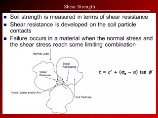
What is Shear Strength? Shear strength in soils is the resistance to movement between particles due to physical bonds from: Particle interlocking Atoms sharing electrons at surface contact points Chemical bonds (cementation) such as crystallized calcium carbonate
Influencing Factors on Shear Strength The shearing strength, is affected by: soil composition: mineralogy, grain size and grain size distribution, shape of particles, pore fluid type and content, ions on grain and in pore fluid. Initial state: State can be describe by terms such as: loose, dense, over-consolidated, normally consolidated, stiff, soft, etc. Structure: Refers to the arrangement of particles within the soil mass; the manner in which the particles are packed or distributed. Features such as layers, voids, pockets, cementation, etc, are part of the structure.
Shear Strength of Soil In reality, a complete shear strength formulation would account for all previously stated factors. Soil behavior is quite complex due to the possible variables stated. Laboratory tests commonly used: Direct Shear Test Unconfined Compression Testing.
Soil Failure and shear strength. Soil failure usually occurs in the form of “shearing” along internal surface within the soil. Thus, structural strength is primarily a function of shear strength. Shear strength is a soils’ ability to resist sliding along internal surfaces within the soil mass.
Slope Stability: Failure is an Example of Shearing Along Internal Surface
failure surface mobilized shear resistance Shear failure Soils generally fail in shear embankment strip footing At failure, shear stress along the failure surface reaches the shear strength.
failure surface Shear failure The soil grains slide over each other along the failure surface. No crushing of individual grains.
Shear failure mechanism At failure, shear stress along the failure surface () reaches the shear strength (f).
Retaining wall Shear failure of soils Soils generally fail in shear
Mobilized shear resistance Failure surface Shear failure of soils Soils generally fail in shear Retaining wall At failure, shear stress along the failure surface (mobilized shear resistance) reaches the shear strength.
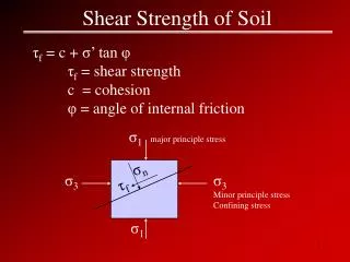
f Mohr-Coulomb Failure Criterion failure envelope friction angle cohesion c f is the maximum shear stress the soil can take without failure, under normal stress of .
failure envelope Friction angle Cohesion f c Mohr-Coulomb Failure Criterion(in terms of total stresses) f is the maximum shear stress the soil can take without failure, under normal stress of .
’ failure envelope Effective cohesion Effective friction angle f c’ ’ ’ Mohr-Coulomb Failure Criterion(in terms of effective stresses) u = pore water pressure f is the maximum shear stress the soil can take without failure, under normal effective stress of ’.
f ’f tan ’ frictional component ’ cohesive component c’ c’ ’f ' Mohr-Coulomb Failure Criterion Shear strength consists of two components: cohesive and frictional.
f f tan frictional component cohesive component c c f Mohr-Coulomb Failure Criterion Shear strength consists of two components: cohesive and frictional. c and are measures of shear strength. Higher the values, higher the shear strength.
Laboratory tests on specimens taken from representative undisturbed samples Field tests • Most common laboratory tests to determine the shear strength parameters are, • Direct shear test • Triaxial shear test • Vane shear test • Torvane • Pocket penetrometer • Fall cone • Pressuremeter • Static cone penetrometer • Standard penetration test Determination of shear strength parameters of soils (c, forc’, f’) Other laboratory tests include, Direct simple shear test, torsional ring shear test, plane strain triaxial test, laboratory vane shear test, laboratory fall cone test
A representative soil sample z z svc + Ds svc shc shc shc shc svc svc + Ds After and during construction Before construction Laboratory tests Field conditions
svc + Ds shc shc Traxial test 0 svc svc + Ds svc shc shc 0 0 t Direct shear test svc 0 t svc Representative soil sample taken from the site Step 1 Set the specimen in the apparatus and apply the initial stress condition Laboratory tests Simulating field conditions in the laboratory Step 2 Apply the corresponding field stress conditions
Direct shear test Schematic diagram of the direct shear apparatus
Porous plates Components of the shear box Preparation of a sand specimen Direct shear test Direct shear test is most suitable for consolidated drained tests specially on granular soils (e.g.: sand) or stiff clays Preparation of a sand specimen
Pressure plate Leveling the top surface of specimen Specimen preparation completed Direct shear test Preparation of a sand specimen
Steel ball P Pressure plate Porous plates S Proving ring to measure shear force Step 1: Apply a vertical load to the specimen and wait for consolidation Direct shear test Test procedure
Steel ball P Test procedure Pressure plate Porous plates S Proving ring to measure shear force Step 1: Apply a vertical load to the specimen and wait for consolidation Direct shear test Step 2: Lower box is subjected to a horizontal displacement at a constant rate
Dial gauge to measure vertical displacement Shear box Proving ring to measure shear force Loading frame to apply vertical load Dial gauge to measure horizontal displacement Direct shear test
Direct shear test Analysis of test results Note: Cross-sectional area of the sample changes with the horizontal displacement
Shear stress, t Dense sand/ OC clay tf Loose sand/ NC clay tf Shear displacement Expansion Dense sand/OC Clay Change in height of the sample Shear displacement Loose sand/NC Clay Compression Direct shear tests on sands Stress-strain relationship
Shear stress, t Normal stress = s3 Normal stress = s2 Shear displacement Normal stress = s1 tf2 tf1 tf3 Shear stress at failure, tf Mohr – Coulomb failure envelope f Normal stress, s Direct shear tests on sands How to determine strength parameters c and f
Some important facts on strength parameters c and f of sand Direct shear tests on sands Direct shear tests are drained and pore water pressures are dissipated, hence u = 0 Sand is cohesionless hence c = 0 Therefore, f’ = f and c’ = c = 0
Overconsolidated clay (c’ ≠ 0) Shear stress at failure, tf Normally consolidated clay (c’ = 0) f’ Normal force, s Direct shear tests on clays In case of clay, horizontal displacement should be applied at a very slow rate to allow dissipation of pore water pressure (therefore, one test would take several days to finish) Failure envelopes for clay from drained direct shear tests
Where, ca = adhesion, d = angle of internal friction Interface tests on direct shear apparatus In many foundation design problems and retaining wall problems, it is required to determine the angle of internal friction between soil and the structural material (concrete, steel or wood)
Piston (to apply deviatoric stress) Failure plane O-ring impervious membrane Soil sample Soil sample at failure Porous stone Perspex cell Water Cell pressure Pore pressure or volume change Back pressure pedestal Triaxial Shear Test
Sampling tubes Sample extruder Triaxial Shear Test Specimen preparation (undisturbed sample)
Setting up the sample in the triaxial cell Edges of the sample are carefully trimmed Triaxial Shear Test Specimen preparation (undisturbed sample)
Sample is covered with a rubber membrane and sealed Cell is completely filled with water Triaxial Shear Test Specimen preparation (undisturbed sample)
Proving ring to measure the deviator load Dial gauge to measure vertical displacement Triaxial Shear Test Specimen preparation (undisturbed sample)
Unconfined Compression Test (UC Test) s1 = sVC + Ds s3 = 0 Confining pressure is zero in the UC test
s1 = sVC + Dsf Shear stress, t s3 = 0 qu Normal stress, s Unconfined Compression Test (UC Test) τf= σ1/2 = qu/2 = cu