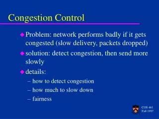
10-Congestion control
10-Congestion control. End-to-end congestion control: no explicit feedback from network congestion inferred from end-system observed loss, delay approach taken by TCP. Network-assisted congestion control: routers provide feedback to end systems bits indicating congestion

10-Congestion control
E N D
Presentation Transcript
10-Congestion control Transport Layer
End-to-end congestion control: no explicit feedback from network congestion inferred from end-system observed loss, delay approach taken by TCP Network-assisted congestion control: routers provide feedback to end systems bits indicating congestion explicit rate sender should send at Approaches towards congestion control Two broad approaches towards congestion control: Transport Layer
ABR: available bit rate: “elastic service” if sender’s path “underloaded”: sender should use available bandwidth if sender’s path congested: sender throttled to minimum guaranteed rate RM (resource management) cells: sent by sender, interspersed with data cells bits in RM cell set by switches (“network-assisted”) RM cells returned to sender by receiver, with bits intact Case study: ATM ABR congestion control Transport Layer
EFCI (explicit forward congestion indication) bit in data cells: set to 1 in congested switch if data cell preceding RM cell has EFCI set, sender sets CI bit in returned RM cell CI(congestion indication) and NI(no increase) bits in RM cells Switch sets NI to 1 (mild congestions) CI bit to 1(severe congestion) two-byte ER (explicit rate) field in RM cell congested switch may lower ER value in cell sender’s send rate thus minimum supportable rate on path Case study: ATM ABR congestion control
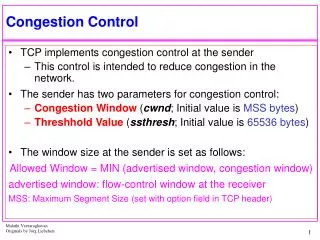
end-end control (no network assistance) How does sender limit the rate? CongWin (congestion window) is dynamic, function of perceived network congestion LastByteSent-LastByteAcked CongWin How does sender perceive congestion? loss event = timeout or 3 duplicate acks Three mechanisms to adapt CongWin: AIMD slow start conservative after timeout events TCP Congestion Control Transport Layer
multiplicative decrease: cut CongWin in half after loss event TCP AIMD additive increase: increase CongWin by 1 MSS every RTT in the absence of loss events Long-lived TCP connection Transport Layer
When connection begins, CongWin = 1 MSS available bandwidth may be >> MSS/RTT desirable to quickly ramp up to respectable rate TCP Slow Start • When connection begins, increase rate exponentially fast until first loss event • For every successful ACK, send two packets. Transport Layer
When connection begins, increase rate exponentially until first loss event: double CongWin every RTT done by incrementing CongWin for every ACK received Summary: initial rate is slow but ramps up exponentially fast Host A Host B one segment RTT two segments four segments time TCP Slow Start (more) Transport Layer
After 3 dup ACKs: (AIMD) CongWin is cut in half window then grows linearly But after timeout event: CongWin instead set to 1 MSS; window then grows exponentially to a threshold, then grows linearly Refinement Philosophy: • 3 dup ACKs indicates network capable of delivering some segments • timeout before 3 dup ACKs is “more alarming” Transport Layer
Q: When should the exponential increase switch to linear? A: When CongWin gets to 1/2 of its value before timeout. Implementation: Variable Threshold At loss event, Threshold is set to 1/2 of CongWin just before loss event Refinement (more) 14 12 10 8 congestion window size (segments) threshold 6 4 2 0 1 2 3 4 5 6 7 8 9 10 11 12 13 14 15 Transmission round Transport Layer
Summary: TCP Congestion Control • When CongWin is below Threshold, sender in slow-start phase, window grows exponentially. • When CongWin is above Threshold, sender is in congestion-avoidance phase, window grows linearly. • When a triple duplicate ACK occurs, Threshold set to CongWin/2 and CongWin set to Threshold. • When timeout occurs, Threshold set to CongWin/2 and CongWin is set to 1 MSS. Transport Layer