Download
1 / 1
10 likes | 163 Vues
This project focuses on improving the Differential Hall Element Magnetometer (DHEM) to enhance its sensitivity and ease of use for high-temperature magnetic materials characterization. Upgrades include the integration of advanced Hall elements and a linear stepper motor for precise data acquisition. Experimental data was collected on a 1970s ceramic speaker magnet, highlighting that the DHEM can be an effective alternative to SQUID magnetometers. Future advancements aim to reduce background signal fluctuations and improve the measurement accuracy of magnetic properties.

E N D
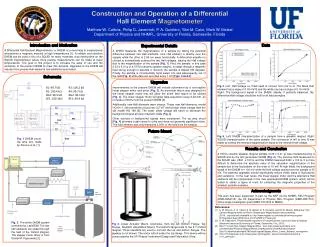
Matthew W. Calkins, Philip D. Javernick, P. A. Quintero, Yitzi M. Calm, Mark W. Meisel Department of Physics and NHMFL, University of Florida, Gainesville, Florida Construction and Operation of a Differential Hall Element Magnetometer Introduction and Motivation A Differential Hall Element Magnetometer, or DHEM, is a novel way to inexpensively characterize a magnetic material at high temperatures [1]. A reliable and sensitive DHEM can be used in lieu of a SQUID for many materials, thus freeing time on the SQUID magnetometer where more precise measurements can be made at lower temperatures. The goal of this project is to increase the ease of use and the sensitivity of the present DHEM to meet this demand. Upgrades to the DHEM will include more precise Hall elements and additional automation. Data Experimental Details A DHEM measures the magnetization of a sample by taking the potential difference between two Hall elements. One Hall element is directly over the sample while the other is 2.54 cm away horizontally. A differential amplifier is utilized to automatically subtract the two Hall voltages, leaving the Hall voltage due to the magnetization of the sample [Fig. 1]. First, the sample, in this case 0.33 ± 0.01 g of a 1970’s ceramic speaker magnet, is swept through a magnetic field strong enough to saturate it. Second, the sample is flipped 180 degrees. Finally, the sample is incrementally hand swept into and subsequently out of the field [Fig. 2] while data are recorded every 1 cm [Figs. 4 and 5]. Schemata Upgrades Improvements to the present DHEM will include automation by a non-captive linear stepper motor and driver [Fig. 2]. An aluminum mount was designed for the linear stepper motor that will allow the entire field region to be utilized [Fig. 3]. The linear stepper motor will allow data acquisition every 0.02 mm, an increase of 500% from the present DHEM [3]. Additionally, new Hall elements were chosen. These new Hall elements, model HQ-0111, offer sensitivity of just over 3.5 V/T and a lower offset voltage than the old model HG 166 [4]. The lower offset voltage will serve to decrease the background signal at lower magnetic fields [Fig. 4]. Other sources of background signals were considered. The op amp circuit [Fig. 4] provides a gain close to unity and does not generate significant noise. The field element also only measures 0.05% of the field from the sample. Fig 4. Left: Hall Voltage vs. Field used to convert from mV to G. The black Hall element has a slope of 0.18 mV/G and the white one has a slope of 0.19 mV/G. Right: The background signal of the DHEM. Ideally, if perfectly balanced, the differential Hall voltage should be null for all field strengths. R1: 99.7 kΩ R2: 100.4 kΩ RG1: 99.5 kΩ RF1: 100.3kΩ R3: 100.2 kΩ R4: 99.7 kΩ RG2: 99.3 kΩ RF2: 99.9 kΩ R1 R2 RF1 RG1 R3 R4 Future Mount RF2 Fig 5. Left: DHEM characterization of a sample from a speaker magnet. Right: SQUID characterization of the same sample. The conversion of mV to emu G was made by setting the remnant magnetization equal to the remnant Hall voltage. Fig. 1 DHEM circuit. Op amp box made by Sincore et al. [1]. RG2 Results and Conclusion A 1970’s ceramic speaker magnet sample (0.33 ± 0.01 g) was characterized by a SQUID and by the first generation DHEM [Fig. 5]. The coercive field measured on the SQUID was 2800 ± 100 G and the DHEM measured 2400 ± 100 G. It is more difficult to determine the absolute value of the saturation magnetization of the sample due to the fluctuations on the order of 10 mV. At high fields, the background signal of the DHEM is ≈ 100 mV while the Hall voltage arising from the sample is 35 mV. The planned upgrades should significantly reduce these types of fluctuations and variations. In the near future, the linear stepper motor and the alternative Hall elements will be incorporated in the new automated DHEM system, which will be tested to obtain a figure of merit for extracting the magnetic properties of the smallest possible samples. Acknowledgments This work has been supported, in part, by the NSF via the NHMFL REU Program (DMR-0654118), the UF Department of Physics REU Program (DMR-0851707), and a single-investigator grant (DMR-0701400 to MWM). Hall Element References: [1] A. M. Sincore, A. Q. Cabra, S. M. Gilbert, E. S. Knowles, and M. W. Meisel, Differential Hall Element Magnetometer for Room Temperature Magnetization Measurements , (2010, unpublished) available at http://www.magnet.fsu.edu/education/reu/program/ 2010/posters/Alex%20Sincore_2010%20REU_Poster.ppt [2] D. M. Pajerowski, Photoinduced magnetism in nanostructures of prussian blue analogues [electronic resource] (University of Florida, Gainesville, Fla., 2010). [3] Size 17 Linear Non-Captive Stepper Motor , see: http://www.haydonkerk.com/ LinearActuatorProducts/StepperMotorLinearActuators/LinearActuatorsHybrid/ Size17LinearActuator/tabid/79/Default.aspx#Stepper_Motor_Linear_Actuator_noncaptive> [4] HQ-0111 Datasheet <http://www.gmw.com/magnetic_sensors/asahi/documents/hq- 0111_gmw.pdf> Fig. 2 The entire DHEM system controlled by LabVIEW. The two hall elements are swept through the field of the Oxford magnet. The stepper motor driver is from Daniel M. Pajerowski [2]. Fig 3. Linear Actuator Mount. Clockwise, from top left: Bottom Flange, Top Flange, Standoff, Assembled Mount. The bottom flange bolts to the 9 T Oxford magnet. Three standoffs are used to connect the top and bottom flanges. The pipekey is not shown. The motor will sit under the top flange. This device will be constructed by the UF Physics Instrument Design and Fabrication Shop. 0-9 T Oxford Magnet