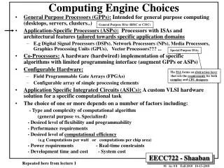
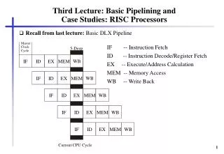
Third Lecture: Basic Pipelining and Case Studies: RISC Processors
Master. IF -- Instruction Fetch. Clock . 5-Deep. Cycle. ID -- Instruction Decode/Register Fetch. WB. IF. ID. EX. MEM. EX -- Execute/Address Calculation. MEM -- Memory Access. WB. IF. ID. EX. MEM. WB -- Write Back. WB. IF. ID. EX. MEM. WB. IF. ID. EX.

Third Lecture: Basic Pipelining and Case Studies: RISC Processors
E N D
Presentation Transcript
Master IF -- Instruction Fetch Clock 5-Deep Cycle ID -- Instruction Decode/Register Fetch WB IF ID EX MEM EX -- Execute/Address Calculation MEM -- Memory Access WB IF ID EX MEM WB -- Write Back WB IF ID EX MEM WB IF ID EX MEM WB IF ID EX MEM Current CPU Cycle Third Lecture: Basic Pipelining and Case Studies: RISC Processors • Recall from last lecture: Basic DLX Pipeline
1.6.3 Control Hazards, Delayed Branch Technique,and Static Branch Prediction • Problem (control conflicts). Control hazards can be caused by jumps and by branches. • Assume Inst1 is a branch instruction. • The branch direction and the branch target address are both computed in EX stage (the branch target address replaces the PC in the MEM stage). • If the branch is taken, the correct instruction sequence can be started with a delay of three cycles since three instructions of the wrong branch path are already loaded in different stages of the pipeline.
branch instruction IF ID EX MEM PC WB branch target instruction IF ID EX MEM WB time three bubbles Bubbles after a taken branch
Solution: Decide branch direction earlier • Calculation of the branch direction and of the branch target address should be done in the pipeline as early as possible. • Best solution: Already in ID stage after the instruction has become recognized as branch instruction.
Solution: Calculation of the branch direction and of the branch target address in ID stage • However, then the ALU can no more be used for calculating the branch target addressa structural hazard, which can be avoided by an additional ALU for the branch target address calculation in ID stage. • And a new unremovable pipeline hazard arises: • An ALU instruction followed by an (indirect) branch on the result of the instruction will incur a data hazard stall even when the result value is forwarded from the EX to the ID stage (similar to the data hazard from a load with a succeeding ALU operation that needs the loaded value). • The main problem with this pipeline reorganization:decode, branch target address calculation, and PC write back within a single pipeline stage a critical path in the decode stage that reduces the cycle rate of the whole pipeline. • Assuming an additional ALU and a write back of the branch target address to the PC already in the ID stage, if the branch is taken, only a one cycle delay slot arises
Software Solution • Delayed jump / branch technique: The compiler fills the delay slot(s) with instructions that are in logical program order before the branch. • The moved instructions within the slots are executed regardless of the branch outcome. • The probability of: • moving one instruction into the delay slot is greater than 60%, • moving two instructions is 20%, • moving three instructions is less than 10%. • The delayed branching was a popular technique in the first generations of scalar RISC processors, e.g. IBM 801, MIPS, RISC I, SPARC. • In superscalar processors, the delayed branch technique complicates the instruction issue logic and the implementation of precise interrupts. However, due to compatibility reasons it is still often in the ISA of some of today's microprocessors, as e.g. SPARC- or MIPS-based processors.
Hardware solution (Interlocking) • interlocking: This is the simplest way to deal with control hazards: the hardware must detect the branch and apply hardware interlocking to stall the next instruction(s).For our base pipeline this produces three bubbles in cases of jump or of (taken) branch instructions (since branch target address is written back to the PC during MEM stage).
Static branch prediction • The prediction direction for an individual branch remains always the same! • the machine cannot dynamically alter the branch prediction (in contrast to dynamic branch prediction which is based on previous branch executions). • So static branch prediction comprises: • machine-fixed prediction (e.g. always predict taken) and • compiler-driven prediction. • If the prediction followed the wrong instruction path, then the wrongly fetched instructions must be squashed from the pipeline.
Static Branch Prediction - machine-fixed • wired taken/not-taken prediction: The static branch prediction can be wired into the processor by predicting that all branches will be taken (or all not taken). • direction based prediction, backward branches are predicted to be taken and forward branches are predicted to be not taken==> helps for loops
Static Branch Prediction- compiler-based • Opcode bit in branch instruction allows the compiler to reverse the hardware prediction. • There are two approaches the compiler can use to statically predict which way a branch will go: • it can examine the program code, • or it can use profile information (collected from earlier runs)
Hardware solutions: BTAC • The BTAC is a set of tuples each of which contains: • Field 1: the address of a branch (or jump) instruction (which was executed in the past), • Field 2: the most recent target address for that branch or jump, • Field 3: information that permits a prediction as to whether or not the branch will be taken. • The BTAC functions as follows: • The IF stage compares PC against the addresses of jump and branch instructions in BTAC (Field 1). ---- Suppose a match: • If the instruction is a jump, then the target address is used as new PC. If the instruction is a branch, a prediction is made based on information from BTAC (Field 3) as to whether the branch is to be taken or not.If predict taken, the most recent branch target address is read from BTAC (Field 2) and used to fetch the target instruction. • Of course, a misprediction may occur. Therefore, when the branch direction is actually known in the MEM stage, the BTAC can be updated with the corrected prediction information and the branch target address.
BTAC (continued) • To keep the size of BTAC small, only predicted taken branch addresses are stored. • Effective with static prediction! • If the hardware alters the prediction direction due to the history of the branch, this kind of branch prediction is called dynamic branch prediction. • Now the branch target address (of "taken") is stored also if the prediction direction may be "not taken". • If the branch target address is removed for branches that are not taken==> BTAC is better utilized • however branch target address must be newly computed if the prediction direction changes to "predict taken"
BTB (Branch target buffer) • BTAC can be extended to implement branch folding: not only the branch target address is stored but also the target instruction itself and possibly a few of its successor instructions. Such a cache is called branch target cache (BTC) or branch target buffer (BTB). • The BTB may have two advantages: • The instruction is fetched from the BTB instead of memory more time can be used for searching a match within the BTB; this allows a larger BTB. • When the target instruction of the jump (or branch) is in BTB, it is fed into the ID stage of the pipeline replacing the jump (or branch) instruction itself.
Multiple-cycle Operations and Out-of-order Execution • Problem (multi-cycle operations): Inst1 and Inst2 , with Inst1 fetched before Inst2, and assume that Inst1 is a long-running (e.g. floating-point) instruction. • Impractical solution: to require that all instructions complete their EX stage in one clock cycle since that would mean accepting a slow clock. • Instead, the EX stage might be allowed to last as many cycles as needed to complete Inst1. • This, however, causes a structural hazard in EX stage because the succeeding instruction Inst2 cannot use the ALU in the next cycle.
div Reg3,Reg11,Reg12 EX MEM WB ... IF ID EX several cycles Register Reg3 later mul Reg3,Reg1,Reg2 IF ID EX MEM WB time Example of a WAW Hazard Caused by a Long-latency Operation and Out-of-order Completion
Solutions to the Problem of Multiple-cycle Operations • interlocking: stall Inst2 in the pipeline until Inst1 leaves the EX stage pipeline bubbles, slow down • a single pipelined FU: general-purpose FU for all kind of instructions slows down execution of simple operations • multiple FUs: Inst2 may proceed to some other FU and overlap its EX stage with the EX stage of Inst1 • out-of-order execution! • instructions complete out of the original program order • WAW hazard caused by output dependence may occur delaying write back of second operation solves WAW hazard further solutions: scoreboarding, Tomasulo, reorder buffer in superscalar • Solutions in the example • delay mul instruction until div instruction has written its result • write back result of mul instruction and purge result of div question: precise interrupt? in case of division by zero
WAR possible?? • WAR may occur if instruction can complete before a previous instruction reads its operand extreme case of o-o-o execution superscalar processors, • not our simple RISC processor which” issues” and starts execution in-order)
Pipelining basics: summary • Hazards limit performance • Structural hazards: need more HW resources • Data hazards: need detection and forwarding • Control hazards: early evaluation, delayed branch, prediction • Compilers may reduce cost of data and control hazards • Compiler Scheduling • Branch delay slots • Static branch prediction • Increasing length of pipe increases impact of hazards; pipelining helps instruction bandwidth, not latency • Multi-cycle operations (floating-point) and interrupts make pipelining harder
1.7 RISC Processors1.7.1 Early RISC Processors • Berkeley RISC I, II SPARC microSPARCII • Stanford MIPS MIPS R3000 MIPS R4000 and 4400 • contrasted to: picoJava I (no RISC, stack architecture)
1.7.3 Case Study: MIPS R3000 • scalar RISC processor introduced in 1995 • most similar to DLX • 5-stage pipeline: IF, ID, EX, MEM, WB; cannot recognize pipeline hazards! • 32-bit instructions with three formats • 32 32-bit registers
Tag(20+4) Address(18) Data(32+4) Virtual Page Number/Virtual Address System Integer Control CPU Unit CP0 Coprocessor CPU Registers Exception/Control Registers ALU Memory Management Local Registers Shifter Control Logic Integer Multiplier/Divider 48-entry TLB Address Adder PC Increment/MUX Master Pipeline/Bus Control Control Case Study: MIPS R3000
1.7.4 Case Study: MIPS R4000 (and R4400) • 8 Stage Pipeline (sometimes called: Superpipeline): • IF: first half of fetching of instruction; PC selection, initiation of instruction cache access. • IS: second half of access to instruction cache. • RF: instruction decode and register fetch, hazard checking, and also instruction cache hit detection. • EX: execution, which includes effective address calculation, ALU operation, and branch target computation and condition evaluation. • DF: data fetch, first half of access to data cache. • DS: second half of access to data cache. • TC: tag check, determine whether the data cache access hit. • WB: write back for loads and register-register operations. • More details in book!
Performance of the MIPS R4000 Pipeline • Four major causes of pipeline stalls or losses: • load stalls: use of a load result one or two cycles after the load • branch stalls: two-cycle stall on every taken branch plus unfilled or cancelled branch delay slots • FP result stalls: because of RAW for a FP operand • FP structural stalls: delays because of issue restrictions arising from conflicts for functional units in the FP pipeline
1.7.6 Java-Processors Overview • Java Virtual Machine and Java Byte Code • Java-processors picoJava-I and microJava 701 • Evaluation with respect to embedded system application • Research idea: Komodo project: Multithreaded Java Core
Stack Architecture: Java Virtual Machine • The Java Virtual Machine is the name of the (abstract) engine that actually executes a Java program compiled to Java byte code. • Characteristics of the JVM: • stack architecture, frames are maintained on the Java stack • no general-purpose registers, but local variables and (frame local) operand stack • some special status infos: top-of-stack-index, thread status info, pointers to current method, method`s class and constant pool, stack-frame pointer, program counter • 8-bit opcode (max. 256 instructions), not enough to support all data types, therefore shorts, bytes and chars are relegated to second class status • escape opcodes for instruction set extensions • data types: boolean, char, byte, short, reference, int, long, float (32 bit) and double (64 bit), both IEEE 754 • big endian (network order: MSB first in the file)
Case study: picoJava-I (and microJava 701) • Applications in Java are compiled to target the Java Virtual Machine. • Java Virtual machine instruction set: Java Byte Code. • Interpreter • Just-in-time compiler • embedded in operating system or Internet browser • Java processors aim at: • direct execution of Java byte code • hardware support for thread synchronization • hardware support for garbage collection • embedded market requirements
I/O bus and memory interface unit 32 32 I-cache (0-16 kB) D-cache PC (0-16 kB) trap 32 control Instruction buffer Instruction Execution D-cache decoding control logic controller and folding 32 Floating-point Stack cache unit Integer unit data path (64 entries) data path 96 picoJava-I Microarchitecture
picoJava-I Microarchitecture Features • instruction cache (optional): up to 16 Kbytes, direct-mapped, 8 byte line size • data cache (optional): up to 16 Kbytes, two-way set-associative write-back, 32 bit line size • 12 byte instruction buffer decouples instruction cache from rest of pipeline,write in: 4 bytes, read out: 5 bytes • instruction format (JVM): 8-bit opcode plus additional bytes, on average 1.8 bytes per instruction • decode up to 5 bytes and send to execution stage (integer unit) • floating-point unit (optional): IEEE 754, single and double precision • branch prediction: predict not taken • core pipeline 4 stages two cycle penalty when branch is taken • branch delay slots can be used by microcode (not available to JVM!!) • hardware stack implements JVM's stack architecture • 64-entry on-chip stack cache instead of register file • managed as circular buffer, top-of-stack pointer wraps around, dribbling
Fetch Execute Decode Write and cache back Execute for one or more cycles Write results back into the operand stack Decode up to two instructions Folding logic Fetch 4-byte cache lines into the instruction buffer picoJava-I Pipeline
Fill . Low . . water mark Parameters and locals D-cache Pipeline -- Operand stack Spill High water mark picoJava-I Stack Architecture & Drippler
picoJava-I Instruction Set • Not all instructions are implemented in hardware. • Most instructions execute in 1 to 3 cycles. • Of the instructions not implemented directly in hardware, those deemed critical for system performance are implemented in microcode. • e.g. method invocation • The remaining instructions are emulated by core traps. • e.g. creating a new object • Additional to JVM: extended instructions in reserved opcode space with 2-byte opcodes (first one of the reserved virtual machine opcode bytes) • for implementation of system-level code (additional instructions not in JVM) • JVM relies on library calls to the underlying operating system • extended byte codes: arbitrary load/store, cache management, internal register access, miscellaneous
Folding + + T T+L0 T+L0 T L0 T L0 L0 L0 L0 L0 Cycle 1: iload_0, iadd Cycle 2: iadd Cycle 1: iload_0 (a) (b) Example of folding (a) without folding, the processor executes iload_0 during the first cycle and iadd during the second cycle (b) with folding, iload_0 and iadd execute in the same cycle
microJava 701 Preview • 32-bit picoJava 2.0 core • Java byte code and C code optimized • 6 stage pipeline • extensive folding allows up to 4 instructions executed per cycle • integrate system functionalities on-chip: memory controller, I/O bus controller • Planned for 1998: 0.25 m CMOS, 2.8 million transistors, 200 MHz • No silicon
picoJava-I Evaluation • Java byte code is extremely dense by stack architecture • picoJava excellent performance compared to Pentium or 486 • short pipeline • hardware stack • dribbler removes register filling/spilling, • folding removes 60% of stack overhead instructions • stack architecture disables most ILP (except for folding which removes some overhead) • not competing with today’s general-purpose processor • but applicable as microcontroller in real-time embedded systems!! • embedded support could be improved, hard real-time requirements not fulfilled • multithreading support may improve • fast event reaction (fast context switching) • and performance (by latency masking)
The Komodo Microcontroller: MT ("Multithreaded") Java Core • start with picoJava-I-style pipeline, extend to multithreading • multiple register sets multiple stack register sets, • IF is able to load from different PCs, (PC, stack reg. ID) is propagated through pipeline • zero-latency context switch • external signals are handled by thread activation, not by interrupting instruction stream • different scheduling schemes • high priority thread runs with full speed, other threads in latency time slots • guaranteed percentage scheduling scheme • multithreading is additionally used whenever a latency arises, e.g. long latency operations • more information (for Studien- and Diplomarbeiten): http://goethe.ira.uka.de/~jkreuzin/komodo/komodoEng.htmlhttp://goethe.ira.uka.de/~jkreuzin/komodo/komodo.html (German version)
Conclusions to Lecture 3 • Simple RISC processors implement pipelining basics • gets more complicated today with • multi-cycle operations • multiple issue • out-of-order issue and execution • dynamic speculation techniques • Java processors are not RISC due to their stack architecture • JVM instructions are not "reduced" • stack register set instead of directly addressable registers • variable-length instructions (compact, but hard to fetch and decode) • Next lecture: Chapter 2: Dataflow Processors