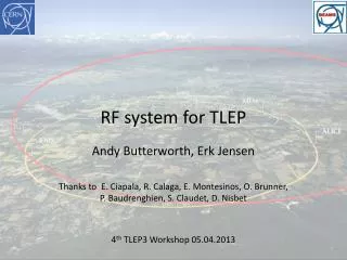
RF system for LEP3 and TLEP
RF system for LEP3 and TLEP. Andy Butterworth (CERN BE/RF) Thanks to E. Ciapala, R. Calaga, E. Montesinos, O. Brunner, P. Baudrenghien, S. Claudet. Overview. Introduction and general considerations A bit of history: the LEP2 RF system Cryogenic cooling capacity

RF system for LEP3 and TLEP
E N D
Presentation Transcript
RF system for LEP3 and TLEP Andy Butterworth (CERN BE/RF) Thanks to E. Ciapala, R. Calaga, E. Montesinos, O. Brunner, P. Baudrenghien, S. Claudet
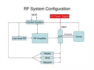
Overview • Introduction and general considerations • A bit of history: the LEP2 RF system • Cryogenic cooling capacity • Technology choices: which is the best fit for a 120 GeVe+e- storage ring? • Producing the voltage • Handling the RF power • Damping higher order modes • Controlling the impedance: Low Level RF • Tentative conclusions
LEP2 SC RF system * Plus 56 copper cavities (130 MV) driven by 8 klystrons
LEP2 SC RF system Design gradient 6 MV/m 1999 2000 1998 * Plus 56 copper cavities (130 MV) driven by 8 klystrons
Introduction The RF system of an e+e- collider has to: • replace the energy lost U0 at each turn by synchrotron radiation • total power needed by the beam = U0 x Ibeam • maintain longitudinal focusing with sufficient momentum acceptance ||max,RFto keep a good beam lifetime, given • the equilibrium energy spread due to quantum excitation/radiation damping (quantum lifetime) • the energy spread (tail) due to beamstrahlung ~
RF voltage • Quantum lifetime is a very steep function of VRF • RF voltage is defined by the momentum acceptance needed to cope with beamstrahlung • 4% for LEP3 • 3% for TLEP-H LEP3: U0 = 7.0 GeV p = 8.1 x 10⁻⁵ E0 = 120 GeV Jz = 1.5 fRF= 352 MHz fRF= 704 MHz fRF= 1300 MHz fRF= 352 MHz fRF= 704 MHz fRF= 1300 MHz δmax,RF~ fRF-1/2 for a given RF voltage
Generalconsiderations (2) • RF frequency: • higher is better, for short bunch length (hourglass effect) • Higher order mode power: • cavity loss factors, bunch length, bunch charge, beam current • power limits of HOM damping • bunch break-up from transverse modes • RF power sources: • klystrons, IOTs, solid state amplifiers? • available power, efficiency, cost • Feedbacks and Low-Level RF: • beamloading(especially if no top-off injection) • longitudinal impedance control (coupled bunch modes)
LHC cryogenic plant capacity • For LEP3 it would be very advantageous if the cryogenic power required for the RF could be supplied by the existing LHC cryogenics plants Total wall-plug power for LHC cryogenics = 40 MW • LHC cold compressors (125 g/s@15mbar=1.8K) have similar dimensions as the CEBAF ones (250g/s@30mbar=2.0K) • However, piping, motors and so on would not be compatible with a factor 2 in capacity. • A more detailed study would be necessary to evaluate the performance we could have if some parts would be changed (motors, bearings, valves,...)
Temperature: Why 2K not 4.5? RF surface resistance Rsurf = Rres + RBCS BCS surface resistance Residual resistance (impurities, trapped flux, etc.) Increases with frequency Increases with temperature
Gradient and dynamic heat load Shorter RF sections Q-slope Lower Q0, higher dissipation margin for microphonics etc. Power dissipation = R/Q depends only on cavity geometry Q0 depends on losses in cavity walls
LEP3/TLEP RF: Potential options ILC collaboration 1300 MHz 9-cell cavity ESS, eRHIC, SPL SPL type cryomodule 704 MHz 5-cell cavity
Option 1: 1.3 GHz TESLA/ILC • ILC cavity performance requirements: Test results for eight 1.3 GHz 9-cell TESLA cavities achieving the ILC specification (DESY) (mounted) BCP + EP
Option 1: 1.3 GHz TESLA/ILC • Promise of even higher cavity performance in future • ongoing R&D in new techniques • e.g. large grain and single crystal niobium cavities Large-grain 9-cell cavities at DESY D. Reschke et al. SRF2011 Single-crystal 9-cell cavities at DESY A Brinkman et al. SRF07
Option 1: 1.3 GHz (LEP3) cf. LEP2: 812 m cf. LHC cryoplant capacity @ 1.9K of 2.4 or 2.1 kW per sector Input power couplers which can handle these CW power levels?
1.3 GHz power couplers • TTF-III couplers tested to 5 kW in CW • 8kW with improved cooling (BESSY) • Some higher power adaptations for ERL injectors • e.g. Cornell 60 kW CW 2 couplers per 2-cell cavity in ERL injector cryomodule Gradient: 5-15MV/m Beam current: 100 mA V. Vescherevitch, ERL’09 Developing a power coupler for 1.3 GHz high gradient and 200 kW CW looks challenging…
Option 2: 704 MHz eRHIC/SPL • BNL 5-cell 704 MHz test cavity (A. Burill, AP Note 376, 2010) SPL/ESS design value 2.0 x 10¹⁰ @ 20MV/m • JLab748 MHz Cavity Test for high-current cryomodule BCP only • First cavities, lots of room for improvement • Measurement after only BCP surface treatment (no EP cf. TESLA cavities) BCP only
Option 2: 704 MHz (LEP3) cf. LEP2: 812 m higher heat load despite higher Q0 because of lower R/Q cf. LHC cryoplant capacity @ 1.9K of 2.4 or 2.1 kW per sector Input power couplers at 704 MHz for these power levels?
704 MHz power couplers • CEA Saclay HIPPI water cooled coupler (SPL/ESS) • tested up to 1.2 MW 10% duty cycle in travelling wave, and 1 MW in standing wave • CERN SPL air-cooled single window coupler • 2 designs currently under test: cylindrical and planar disk windows • design goal: 1 MW 10% duty cycle for SPL • cylindrical window design uses LHC coupler ceramic window with tapered outer conductor • LHC windows are routinely tested to > 500 kW CW Coaxial disk ceramic window Cylindrical ceramic window E. Montesinos
704 MHz power couplers Latest R&D results High average power air cooled couplers (CERN BE-RF-PM) • Cylindrical window : • TW : 1000 kW 2 ms 20 Hz • SW : 550 kW 500 us 8 Hz • Coaxial disk window : • TW : 1000 kW 2 ms 20 Hz • SW : 1000 kW 1.5 ms 20 Hz 40 kW average power Limited by arcing on air side of window Improvements in window air flow and screen at braze 40 kW average power Limited by losses in uncoated outer double walled tube Improvements in coating
TLEP-H cf. LEP2: 812 m • Limited by power per cavity • Install twice the # cavities with half the gradient? Very high power levels! (2 x LEP3)
Top-up injector rings • SR power very small • (beam current ~ 1% of collider ring) • Average cryogenic heat load very small • (duty cycle < 10%) • Power is dominated by ramp acceleration: • for a 1.6 second ramp length: Well within our 200 kW budget
Higher order mode power R. Calaga Cavity loss factors Average PHOM = k||.Qbunch.Ibeam k|| = 8.19 V/pC k|| = 2.64 V/pC • HOM powers in the kW range to remove from the cavity at 2K
HOM power “league table” LEP3 704 MHz 14 6,100 TLEP-H 704 MHz 49 10,400 LEP3 1.3 GHz 14 18,800 TLEP-H 1.3 GHz 49 32,100 After M. Liepe, SRF2011
KEKB SC cavity HOM dampers • 509 MHz single cell cavity • Iris diameter 220 mm • Ferrite HOM absorbers on both sides (outside cryostat) • HOM power: 16 kW/cavity Y. Morita et al., IPAC10, Kyoto
HOM power “league table” eRHIC /SPL/ESS 704 MHz cavities LEP3 704 MHz 14 6,100 TLEP-H 704 MHz 49 10,400 LEP3 1.3 GHz 14 18,800 TLEP-H 1.3 GHz 49 32,100 After M. Liepe, SRF2011
5-cell SRF cavity with strongHOM damping for eRHIC at BNL HOM high-pass filter HOM ports F = 703.5MHz HOM couplers: 6 of antenna-type Fundamental supression: two-stage high-pass filters Eacc = 20 MV/m Design HOM power: 7.5 kW FPC port • BNL3cavity optimized for high-current applications such as eRHIC and SPL. • Three antenna-type HOM couplers attached to large diameter beam pipes at each end of the cavity provide strong damping • A two-stage high-pass filter rejects fundamental frequency, allows propagation of HOMs toward an RF load. M. Tigner, G. Hoffstaetter, SRF2011, W. Xu et al, SRF2011
HOM power “league table” due to higher beam intensity. needs study LEP3 704 MHz 14 6,100 TLEP-H 704 MHz 49 10,400 LEP3 1.3 GHz 14 18,800 TLEP-H 1.3 GHz 49 32,100 After M. Liepe, SRF2011
RF power sources • “Super-power” klystrons at 700 MHz • Multiple cavities per klystron as in LEP2 • Could perhaps use IOTs (inductive output tubes) or solid state amplifiers for the injector ring (lower power required)
LLRF: instabilities and feedbacks • LEP2: • slow scalar sum feedback acting on the klystron modulation anode, with the klystrons operated at saturation for maximum efficiency • Fast RF feedback may be desirable • especially for TLEP where frev is lower, detuning may drive coupled bunch modes • Beamloading: “second Robinson” instability • loss of longitudinal focusing due to large detune angle under strong beamloading • occurs at low RF voltage with high beam current • seen in LEP2 at injection energy • cured by using fast RF feedback on a few RF stations • an issue if we don’t have top-up injection Becomes unstable when VG is in antiphase with IB Second Robinson 1st Robinson
Tentative conclusions • We cannot use ILC technology “off the shelf” • power coupler limitations • loss factors and HOM damping • Backing off in frequency to 700 MHz seems preferable • ongoing R&D at BNL, CERN, ESS for 704 MHz cavities and components • fundamental power couplers look feasible at > 200 kW CW • compatible with HOM damping scheme for eRHIC • high-power klystrons available • Cryogenic power will probably fit into the envelope of the existing LHC cryoplants (for LEP3) • Open questions • power coupler design • HOM damping (especially for TLEP) • low level RF & feedback requirements An RF system for a circular Higgs factory such as LEP3 or TLEP is not without its challenges but appears to be very feasible, especially as there are strong synergies with other ongoing development projects.
SPS 800 MHz TWC prototype feedback board G. Hagmann BE-RF-FB designer
Carnot ~150 @ 2K Eff. ~ 30% of Carnot Total wall-plug power for LHC cryogenics = 40 MW