Transformer
Transformer. DEFINATION. Transformer is a static piece of apparatus by means of which power in one circuit is transformed into electric power of the same frequency in another circuit. Working Principle.


Transformer
E N D
Presentation Transcript
DEFINATION Transformer is a static piece of apparatus by means of which power in one circuit is transformed into electric power of the same frequency in another circuit.
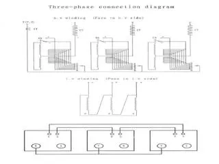
WorkingPrinciple It consists of two inductive coils which are electrically separated but magnetically linked. The two coils possess high mutual inductance. If one coil is connected to a source of alternating voltage, an alternating flux is set up in the laminated core, most of which is linked with the other coil in which it produces mutually induced e.m.f according to Faraday’s laws. If the second coil ckt is closed a current flows in it and electric energy is transferred from the first coil to second coil. The first coil, in which electric energy is fed from the ac supply mains, is called the primary winding and the other from which energy is drawn out, is called secondary winding.
Transformer In brief, a transformer is a device that • TX transfers electric power from one ckt to another. • It does so without a change of frequency. • It accomplishes this by electromagnetic induction. • Where the two electric ckt are in mutual inductive influence of each other.
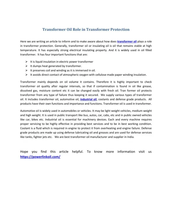
Components of a Transformer • Winding • Iron core • Transformer tank • Yoke • Conservator • Transformer Oil • Bushing • Oil level indicator • Breather • Radiator tubes for cooling • Tap changer • Buchholz relay
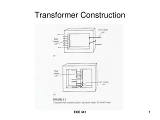
Transformer Construction The simple element of a transformer consists of two coils having mutual inductance and a laminated steel core. Necessary part are: • Some suitable container for assemble core and winding • A suitable medium for insulating the core and its winding from container • Suitable bushing for insulating and bringing out the terminals of winding from the tank.
Transformer Construction The eddy current loss is minimize by laminating the core, the lamination being insulated from each other by alight coat of core- plate vanish or by an oxide layer on the surface. The thickness 0.35mm for 50Hz frequency 0.50 for 25Hz frequency
Transformer Construction Constructionally, the TX are of two general types. The two type are known as : • Core-type Transformer • Shell-type Transformer • Core-type Transformer-Winding surrounds a considerable part of Core. • Shell-type Transformer-Core Surrounds a considerable part of Winding.
Bushing • The bushing provides insulation of the terminals of winding. These bushings are made of well china clay. These are housed on the upper side of tank through gasket. Service line and terminals of the winding is connected through bushing. • High side bushings are large and low side bushings are small Low voltage bushing High voltage bushing
Conservator • It is transformer oil storage tank and if the main tank oil reduces the conservator will feed the oil to main tank. • And if the oil get expansion that oil will go to conservator Fig: Conservator
Breather • A transformer breather is an accessory of an oil filled type transformer which is attached into the oil conservator tank. • It protect moisture entering the conservator tank. • In the refrigeration breather system, an air dryer is fitted to the conservator vessel. Fig: Breather
Elementary Theory of an Ideal Transformer • An ideal Transformer is one which has no magnetic leakage and hence which has no cupper and core losses.
E.M.F Equation of a Transformer Let • N1= No of turns in primary • N2= No of turns secondary • Φm=maximum flux in core
Transformer on No-load At no-load condition the primary current has to supply • Iron loss in core i.e hysteresis loss and eddy current loss • Small amount of copper loss in primary
Transformer on load When the secondary is loaded the magnitude & phase of I2 with respect to v2 is determined by the characteristic of the load. • Current I2 is phase with v2 if load is non inductive • It lags if load is inductive • It leads if load is capacitive
Vector diagram for a loaded transformer The total primary current is the vector sum of I0 and
Magnetic leakage The flux linked with primary does not link the secondary but part of it complete its magnetic circuit by passing through air rather the core. This flux is known as leakage flux. This flux is directly proportional to the e primary ampere turn.
Leakage flux equivalent circuit A transformer with magnetic leakage is equivalent to an ideal transformer with inductive coils connected in both primary and secondary circuits.
Equivalent circuit of transformer with resistance and leakage reactance
Transformer test The purpose of this is to determine core loss. High voltage winding left open and other is connected to its supply of normal voltage and frequency. No load current is small(2 to 10% of rated current) Cu loss is negligible small in primary and nil in secondary.
Short-circuit or impedance test Purpose of this test is to determine copper loss at full load A low voltage (usually 5 to 10% of primary voltage) is applied to the primary and is cautiously till full-load current are flowing both in primary and secondary.
Why transformer rating KVA? Cu loss of transformer depends on current Iron or core loss depend on voltage Total loss depend on volt-ampere(VA) and not on phase angle between V & I i.e it is independent of load power factor. That is Why transformer rating KVA not kw.
Losses in transformer In static transformer , there are no friction or windage losses. • Core or iron loss • Cupper loss Core loss two types Hysteresis & Eddy current loss
Auto-transformer It is a transformer with one winding only, part of this being common to both primary and secondary. The primary and secondary are not electrically isolated from each other.
Uses of transformer To give small boost to a distribution cable to correct the voltage drop. As auto- starter transformer to give upto 50 to 60% of full voltage to an induction during starting.
Parallel operation of single-phase transformer For supplying a load in excess of the rating , we have to connect more transformer in parallel.
Condition of parallel operation Primary winding of the transformer should be suitable for the supply system voltage & frequency The transformer should be properly connected with regard polarity. The voltage rating of both primaries and secondary's should be identical. The percentage impedance should be equal in magnitude and have same X/R ratio in order to avoid circulating currents and operation at different power factor. With transformer having different kVA ratings, the equivalent impedance should be inversely proportional to the individual kVA rating.