Transformer Types, Construction, and Efficiency Calculation Examples
This document covers various transformer types, including tapped windings, iron-cored, ferrite-cored, auto-transformers, and multiple-windings. It provides detailed calculations for the voltage regulation and efficiency of transformers under full-load and half-load conditions, using specific resistance and reactance values. Example scenarios feature transformers rated at 30 kVA and 500 kVA, highlighting core losses and wire losses, along with how they affect performance based on different power factors.


Transformer Types, Construction, and Efficiency Calculation Examples
E N D
Presentation Transcript
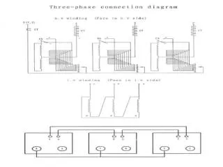
(d) Tapped -windings (a) Iron-cored Transformer F B E D A C (b) Ferrite –cored Transformer (e) Auto-Transformer C B A (c) Multiple-windings H G B F E A D C Types of transformer
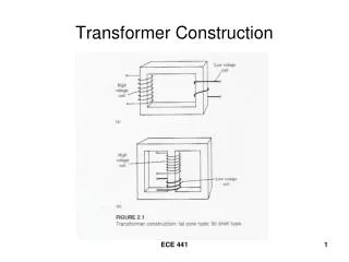
Construction of transformer Laminated steel-core transformer
6000/230 V I1 R1 Xe R2 I2 10 23 0.016 V1 V1’ V2’ V2 30 kVA Example 5 Primary windings of a 30 kVA, 6000 V/230 V transformer has a resistance of 10 , the secondary windings has a resistance of 0.016 . The total reactance of the transformer referred to primary is 23 . Calculate the voltage regulation of the transformer when it supplies a the full-load current at power factor of 0.8 lagging
I1 Re Xe 6000/230 V I2 V1 V1’ V2’ V2 30 kVA Equivalent resistance of primary and secondary referred to primary is Full-load current at primary
Efficiency • Losses in transformer on load categorized into two • I2R losses in primary and secondary windings, namely I12R1+I22R2. • Core losses due to hysteresis and eddy currents Usually variation between no-load and full-load can be negligible thus, the total core loss, PC , is assumed to be constant all the time. Therefore total loss or R1e=equivalent resistance of primary and secondary referred to primary R2e=equivalent resistance of primary and secondary referred to secondary
Note: p.f= power factor The wire losses can be expressed as Divided by I2
Example 6 The primary and secondary windings of a 500 kVA transformer have a resistances of 0.42 and 0.0011 respectively. The primary and secondary voltages are 6600 V and 400 V respectively and the core loss is 2.9 kW , assuming the power factor of the load to be 0.8. Calculate the efficiency on (a) full-load and (b) half-load. (c) assuming the power factor 0.8, find output which the efficiency of the transformer is maximum. (a) Primary current on full-load Secondary current on full-load Coil Wire loss at primary PW1=I12R1=75.82 x 0.42=2415W Coil Wire loss at secondary PW2=I22R2=12502 x 0.0011=1720W
PW = PW1 + PW2 = 2415 + 1720 = 4.135kW Total loss PL= PW + PC = 4.135 + 2.9 = 7.035kW Output power on full load Pout = 500 x 0.8 = 400 kW Therefore Pin = Pout + PL = 400+7.035 = 407.035 kW
(b) Since the wire loss varies as square of the current , thus Losses on half-load PW/2=4.135/22=4.135/4=1.034kW Total Loss on half-load PL= PC+PW/2=2.9+1.034=3.934kW Output power on half-load Pout/2= 400/2 = 200kW Input power on half-load Pin/2= Pout/2+PL=200+3.934 = 203.934kW
(c) Full-load I2R loss is PW = 4.135kW Let n= fraction of full-load appearance power at which it is maximum efficiency Total I2R loss is = n2 x 4.135 kW=2.9 Therefore n=0.837 Output at maximum efficiency is= 0.837 x 500= 418.5kWA Output power at power factor 0.8= 418.5 x 0.8 = 334.8 kWA Since the core and I2R are equaled, then total loss is PL= 2 x 2.9 = 5.8 kW