Download
1 / 17
170 likes | 189 Vues
This article explores the use of liquid walls in direct-drive laser fusion chambers as an alternative to gas-protected dry walls. It discusses the advantages of liquid walls, such as rapid replaceability and resistance to neutron damage, and the limitations of dry walls, including thermal damage and erosion. The phenomenon of vaporization and condensation in liquid walls is also examined, along with its impact on chamber design. The ZP3 concept, which utilizes thick liquid wall protection, is presented, as well as target simulations and analysis of shock waves and pressures within the materials. The need for further validation and extending the use of the BUCKY code is discussed.

E N D
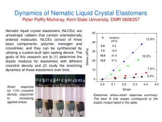
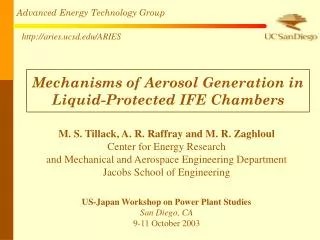
Dynamics of Liquid Wall Chambers R.R. Peterson, I.E. Golovkin, and D.A. Haynes University of Wisconsin ARIES Meeting Madison, WI April 22 and 23, 2002
Why Are Liquid Walls Considered When Gas-Protected Dry-Walls Can Work for Direct-Drive Laser Fusion and Are Simpler?
Liquid Walls Are Intended To Vaporize While Dry Walls Must Not • Liquid walls may be rapidly replaceable, either as a surface film or as free-standing jets. • Liquid walls are not subject to neutron damage, sputtering, and blistering, which are all important issues for dry walls. • Thermal damage and erosion are serious issues for dry-walls (< 1 mono-layer of erosion allowed per shot) but are not an issue for liquid walls. • Target remnants can be captured by liquid. • Condensation of vapor and removable of aerosols and splashed chunks limits rep-rate.
Liquid Wall Phenomenology Drives IFE Chamber Design • Chamber gas/vapor density at beam transport (HIB: channel, self-pinched or ballistic; Laser) has limits. • Gas in chamber at time of target explosion can partially protect liquid from vaporization (LIBRA). • Vaporization induces strong shocks in the liquid that impart large impulses and high pressures to structures • Blow-off vapor exhibits complex behavior, including nucleate condensation into aerosols, absorption of late x-rays and ions from the target, and re-radiation of energy to the liquid surface. • Condensation of vapor limits rep-rate and is enhanced by large surface area (HYLIFE, HIBALL, …) and large thermal velocity of vapor atoms (Li versus Pb). • Aerosol dynamics will also limit rep-rate.
ZP3 Concept Extends the Recent Exciting Results of Pulsed-Power Driven ICF Physics to a Power Plant Replaceable Inner MILT and Power Flow Wire-Array Hohlraum and IFE Capsule Z-like Insulator Stack and MILT
ZP3, a Z-Pinch Power Plantis a New Example of Thick Liquid Wall Protection
1-D BUCKY Calculations for ZP3 Are Performed For Two Cases: With and Without Liquid Protection • 1-D spherical geometry • Preliminary: Li instead of Flibe (we now have Flibe opacity) • ~900 MJ in x-rays • ~100 MJ in Pb ions • Chamber interior temperature – 600oC ¼ atm He Down into Pool Li 50cm 200cm Without liquid ¼ atm He Steel Target 250cm 50cm
Implosion without hohlraum; radiation drive Final implosion and burn with hohlraum; no drive BUCKY Target Simulations of X-1 Output Were Scaled From 400 MJ to 4 GJ Au BeO BeO Be98O2 DT DT
BUCKY Target Simulation of X-1 (400 MJ) Output Shows Two Major Pulses: Direct Emission from Capsule and From Capsule Kinetic Energy Converted to Radiation by Hohlraum • If the Hohlraum is cylindrical, the 2nd pulse will be more spread-out. • Emissions may be anisotropic (NIF target is). Spectrum is about a 1 keV BB
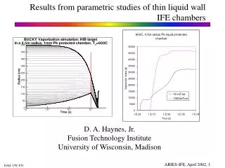
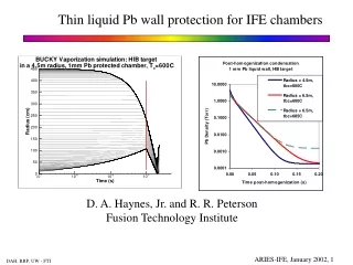
X-rays vaporize material from the surface 38,000 J/cm2 1,500 J/cm2 Non-neutronic fluence Even though Steel experiences much less vaporization depth, the total mass vaporized is greater. Li at 50 cm Steel at 250 cm ~ 3.5 mm ~ 0.02 mm Thickness of vaporized material
Recoil Pressure From Intense Vaporization Drives Shock Wave Propagation in the Materials Vaporization driven shock structure in Lithium is initially complex but it smoothes as it moves into the fluid. Li Layer 50 cm Steel at 250 cm
Pressure Within Lithium Shows Multiple Shocks Decaying at Increasing Depth Pressure temporal profiles at different depths (Li) • Importance of dissipation. • At 1 cm into Li, initial shock is 115 kbar in < 1 s. • 10 cm into Li, shock pressure is still 45 kbar and is spread over 7 s. • Eventually shocks coalesce.
Impulse is Conserved As Shock Moves into Lithium Maximum pressure and corresponding impulse at the back surface for different thickness of Li layer
Analysis of Liquid Wall Chamber Concepts Needs Validation • Validation of BUCKY has been in progress for about 15 years. • Fireball experiments on Pharos-II. • X-ray vaporization experiments on Nova, Helen, Saturn, and Z. • Ion vaporization experiments on RHEPP. • Additional validation is needed. • Wall condensation • Nucleate condensation • X-ray driven shock impulse measurements. • Fireball radiation (what can we learn from Tokamak disruption experiments?) • Target output spectra
Proposed new role for BUCKY • Extend BUCKY to community code status • Restricted access to BUCKY collaborators, who are expected to help with validation and/or new models • Extend documentation • Example input files and data files for many types of calculations • Web interface to conveniently submit jobs and retrieve results • BUCKY application server at UW
PHD-IV • TN burn • Gray Radiation Diffusion • 1-D Lagrangian Hydro • Te Ti • FIRE • Start with PHD-IV • Remove TN burn • Multi-group Diffusion • X-ray and ion energy sources • Te = Ti • CONRAD • Start with FIRE • Vaporization and Condensation by Chamber Wall • BUCKY • Combine PHD-IV and CONRAD • TN burn • Multi-group Diffusion • Laser deposition • Te Ti • Time-dependent CRE radiation transport • Vaporizing IFE chamber walls • Tokamak disruption divertor vaporization • NIF Capsules • NIF chamber wall • experiments • NRL laser targets • Z experiments • ARIES target chamber Target Implosion, Burn, Explosion Gas filled target chambers PHD-IV FIRE CONRAD BUCKY BUCKY Has Been Under Development for About 3 Decades 1980 1985 1990 1995 2000 1975
MIXERG • Gray and Multi-group Opacities for FIRE • Rosseland and Planck • Semi-Classical absorption coefficients • Tabulated ionization energies • Saha or Coronal Ionization • Self-consistent ionization for mixtures • EOS: ideal gas + ionization and excitations • IONMIX • MIXERG + • Non-LTE Ionization • Multi-group • Rosseland and Planck absorption and emission • EOSOPA • Hartree-Fock (Cowan) atomic structure • LS coupling • UTA or DCA/LTE or CRE for Z ( 18) • UTA/LTE for Z (18) • Creates data for CRE in BUCKY • Pressure ionization • Muffin-Tin EOS • JATBASE • JAVA interface for EOSOPA • User friendly • RSSOPA • Relativistic (Dirac eqn.) • JJ coupling • SOSH UTA’s JATBASE RSSOPA EOSOPA MIXERG IONMIX EOS and Opacity Codes for BUCKY have Also been written over a long time 1980 1985 1990 1995 2000 1975