Download
1 / 28
280 likes | 307 Vues
Experimental research work on flibe vapor condensation rates relevant to fusion technology, proposing innovative vapor generation schemes for liquid protection. Study includes findings on inhibiting vapor condensation on metal surfaces and optimizing vapor expansion volume.

E N D
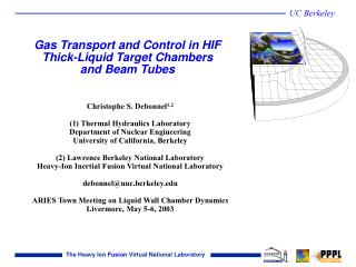
Vapor Condensation Study for HIF Liquid Chambers by Patrick Calderoni UCLA – Fusion Engineering Sciences 15th International Symposium on Heavy Ion Inertial Fusion Princeton Plasma Physics Laboratory Princeton, NJ, June 7-11, 2004
Experimental research work major accomplishments Developed an innovative and inexpensive scheme to generate flibe vapor in conditions relevant to fusion technology design studies involving a liquid protection scheme (HIF, IFE, Z-pinch) Measured flibe vapor clearing rates suggest that high repetition rates in HIF power plants are feasible provided that high purity of the molten salt is ensured Found that for flow conditions characterized by high kinetic energy flibe vapor condensation is partially inhibited on metal surfaces perpendicular to the main component of the vapor velocity
HYLIFE-II parameters relevant to vapor condensation studies (Moir, 1994) Total mass generated from x-ray absorption on liquid surfaces: 14 kg Total volume for vapor expansion: 280 m3 Initial n: 0.9x10¹⁸ #/cm3(0.5x1018 #/cm3) Recovered n:3x10¹³ #/cm3 (2x10¹⁵ #/cm3) Energy from explosion coupled with x-ray and debris: 110 MJ Energy density: 7.85 kJ/g (7.5 kJ/g) Structural surface for condensation: 40 m2 Surface from droplet injection: 1060 m2 Ratio of surface area per unit mass of generated vapor: 785 cm2/g(4300 cm2/g for LiF and 10205 cm2/g for flibe) Droplet spray injection design: T = 843 K Spray flow rate = 2.4x10³ kg/s (1.6% of main flow rate)
Experimental approach: staged design of vapor generation facility Characterization of superheated vapor source in comparison to other experiments using electro-thermal sources Limited availability, cost and toxicity of materials: demonstrate efficiency, repeatability and reliability before using flibe Reduce residual non-condensable gases Diagnostic development
time: 0 Stage 1: Lexan with Argon background (1 Torr) time: 820 s Typical vapor parameters in the source : n = 1019 - 1020 # / cm3 T = 1-3 eV time: 1640 s Argon background is ionized (10-100 ns) forming initial plasma column Energy stored in cap banks maintains plasma at 1-3 eV for 100 micros Injected electrical power radiated to surface, ablates material of interest Pressure gradient drives injection, ablation balances axial mass loss
Stage 2: Teflon and LiF in vacuum chamber current in vapor source current out time of flight view ports expansion chamber volume: 4000 cm3 surface area: 1720 cm2
Cathode: ¼’’ D 10’’ long W rod Stage 3: Flibe vapor generation Total length: 34 cm Expansion volume: 400 cm3 Surface area: 420 cm2 SS witness plates for SEM and EDX analysis Insulation: high-vacuum ceramic breaks Pressure sensor, water cooled (Tmax = 260 C) Flibe liquid pool: 1.6 cm3 volume Anode: Nickel crucible with embedded high density cartridge heater
High-speed camera frames sequence from flibe discharge 220 s 100 s 120 s 240 s 260 s 140 s 160 s 280 s 300 s 180 s 320 s 200 s
Pressure data and residual gas composition: flibe condensation is completed in 30 ms: no residual BeF2 traces at 47 amu t500 = 6.58 ms t300 = 4.27 ms (4.22 ms at 1.44 kJ) 300 C 500 C H2 28,16 amu: hydrocarbons 44 amu: CO2
Comparison with HYLIFE-II chamber clearing models p(T) → n(T) assumes thermodynamic equilibrium with a liquid surface n = n0 x e-t/T n0 = 0.9x10¹⁸ #/cm3 nend = 3x10¹³ #/cm3 Clearing period for HYLIFE-II = 68 ms
Measured composition of flibe vapors in equilibrium with a liquid surface hydrocarbons CO2 H2 BeF2 at 460 C Heating sequence (linear) from 460 C to 700 C (about 30 min)
Additional data: post-analysis of side collecting plates Collecting plates parallel to the radial direction Surfaces are gold plated for SEM analysis Film forms during first expansion phase (100 s) when vapor velocity is highly directional At low T film is thinner and breaks due to quick cooling and solidification 460 C 300 C Drops condense in the chamber volume after the velocity has become uniform and deposit on the liquid film without merging
Additional data: post-analysis of front collecting plates Collecting plates perpendicular to the radial direction Film condensation is inhibited at 300 C 300 C 460 C At 460 C thin film starts at fixed r from plate side center (flow stagnation point) EDX analysis confirms qualitative results
Additional data: post-analysis of collecting plates Further evidence of volumetric condensation 300 C 300 C side plate front plate 460 C Evidence of liquid displacement by the pressure front generated during the discharge: large liquid drops are entrained in the flow and deposit around the crucible and the collecting plates Large drop is flibe
Conclusion Condensation rates of flibe vapor in conditions relevant to IFE power plant studies have been measured experimentally - Vapor density decays exponentially with a time constant of 6.58 ms in the range between 5x1017 cm-3 and 2x1015 cm-3 Extending to HYLIFE-II expected density cycles the vapor clearing rate is 68 ms, compatible with the desired 6 Hz repetition rate Data suggest that for flow conditions characterized by high kinetic energy flibe vapor condensation is partially inhibited on surfaces normal to the main component of the vapor velocity Control of the impurities dissolved in the molten salt is a fundamental issue for applications that require recovery of vacuum conditions in the 1013 #/cm3 range
Discharge parameters Teflon I and V for 10 and 5 disk configuration LiF I for different energy experiments I for flibe experiments
Liquid protection for Inertial Fusion Energy power plant chambers HYLIFE-II concept Neutron damages and activation of flowing liquid accumulate only in the short residence period - no blanket replacement required, increases availability Thick liquid “pockets” or thin liquid layers shield chamber structures: fluid mechanics questions replace materials questions
High Tritium Breeding Ratio Low electrical conductivity High neutronic thickness Chemical, radioactive and thermal stability The molten salt flibe: For fusion system design: For small scale experiments: Limited material availability Beryllium safety hazard Uncertain composition and purity level of available material Lack of data on physical and chemical properties
Flibe composition is a compromise between melting temperature (structural costs) and viscosity (pumping cost) 2 LiF + 1 BeF2 in moles
Flibe low vapor pressure is a key property for efficient driver coupling with the fusion target at high repetition rates Reference data for flibe vapors are based on the assumption of thermodynamic equilibrium at the liquid interface and ideal gas equation In equilibrium with the liquid at 600 C, flibe vapor pressure is about 1 mTorr, corresponding to a density of 1.2 1013 cm-3
Weight loss measurements 18 experimental runs with 10 Teflon disks as sleeve material 1 with 5 disks 5.76 kJ 2.54 kJ Volume ratio between source and chamber: 1:25 Evidence of C soot deposition on source component
Dynamic sensor mounted at center of back plate (high noise from vibration) Pressure data: Lexan and Teflon about 5 times decay Teflon = CF2 chain Residual gases (20-70 Torr): 28 amu (C2H2 - C2H4 - C2H6) 69 amu (CF4) 20 amu (HF)
Jet velocity optical measurement system Diode axis separation: 7.62 cm Peak time delay: 6 microseconds Estimated initial vapor velocity: 10110 m/s
Jet velocity optical measurement system Sensor closer to center of chamber sees a second peak in the light, about 2ms after triggering Peak due to first reflection of the vapor jet at the chamber bottom Vapor cools and expands in the chamber, emitting front does not reach the upper sensor Estimated average velocity of vapor in the chamber after first reflection: 320 m/s - 4 kV 210 m/s - 3 kV
Flibe experiments results Exponential decay fits data points good Decay time constant t1 is a measure of the condensation rate t1 = 4.22 ms
Flibe experiments results Exponential decay fits data points good Decay time constant t1 is independent from initial particle density t1 = 4.27 ms
Additional data: emission spectroscopy Strong lines from neutral and first ionization state of both lithium and beryllium atoms are present in the spectrum • Be vapors diagnostic development: • measure at different times the ratio of line intensity of Li I and Li II transitions • steady-state emission calibration with langmuir probe will associate line ratio with thermodynamic vapor parameters (pressure and density)