Appendix B
Appendix B. Object-Oriented Analysis and Design. Learning Objectives. Understand the basic characteristics and objectives of the object-oriented approach to software development Identify the component elements of object-oriented software design. Learning Objectives.

Appendix B
E N D
Presentation Transcript
Appendix B Object-Oriented Analysis and Design
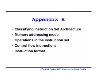
Learning Objectives • Understand the basic characteristics and objectives of the object-oriented approach to software development • Identify the component elements of object-oriented software design SAD/APPENDIX_B
Learning Objectives • Understand the Unified Modeling Language (UML) and its relationship to object-oriented design • Explore the various diagrams and their applications contained within the UML SAD/APPENDIX_B
Introduction • Object-oriented approach to software development • Views the system as a collection of self-contained modules, or objects, that carry with them both the processes necessary to execute their intended role and the data necessary for that execution SAD/APPENDIX_B
The Concepts of Object-Orientation • Object • Any person, place, thing, or event about which we wish to store data or capture its behavior • Attributes • Current state • Behavior • Unique Identifier (UID) SAD/APPENDIX_B
Figure B-1. Objects, Attributes, Methods, and Instances SAD/APPENDIX_B
Figure B-2. Software Object Representation of a Bicycle SAD/APPENDIX_B
The Concepts of Object-Orientation • Object • Encapsulation • Object encapsulates both data and implementation • The user can view the object as a black box • Modularity • Information Hiding SAD/APPENDIX_B
The Concepts of Object-Orientation • Class • Blueprint or prototype that defines the variables and the methods common to all objects of a certain kind • Generalized description for objects that are similar in nature or share many of the same characteristics SAD/APPENDIX_B
Figure B-3. Blueprint Concept of a Software Object SAD/APPENDIX_B
Figure B-4. Example of Object Class Implementations SAD/APPENDIX_B
Figure B-5. Instance Objects Created From BICYCLE Class SAD/APPENDIX_B
Figure B-6. Example of Instance Derived From Object Class SAD/APPENDIX_B
The Concepts of Object-Orientation • Hierarchical Inheritance • Each subclass inherits state and methods from the superclass • Subclass can add variables and methods to the ones they inherit from the superclass SAD/APPENDIX_B
Figure B-7. Hierarchical Inheritance – Superclass and Subclasses SAD/APPENDIX_B
The Concepts of Object-Orientation • Messages • Objects interact and communicate with each other by sending messages • Additional information can be passed along with the message (parameter) SAD/APPENDIX_B
Figure B-8. Example of Object Messaging SAD/APPENDIX_B
The Concepts of Object-Orientation • Polymorphism • A message to one object could invoke different behavior than the same message to a different object • The requesting object does not need any information with regard to how that behavior is accomplished SAD/APPENDIX_B
Unified Modeling Language • Within a system-intensive process, a method is applied as a process to derive or evolve a system. • As a language, it is used for communication. That is, a means to capture knowledge (semantics) about a subject and express knowledge (syntax) regarding the subject for the purpose of communication. The subject is the system under discussion. SAD/APPENDIX_B
Unified Modeling Language • As a modeling language, it focuses on understanding a subject via the formulation of a model of the subject (and its related context). The model embodies knowledge regarding the subject, and the appropriate application of this knowledge constitutes intelligence. • Regarding unification, it unifies the information systems and technology industry’s best engineering practices across types of systems (software and non-software), domains (business versus software), and life-cycle processes. SAD/APPENDIX_B
Unified Modeling Language • As it applies to specifying systems, it can be used to communicate "what" is required of a system, and "how" a system may be realized. • As it applies to visualizing systems, it can be used to visually depict a system before it is realized. SAD/APPENDIX_B
Unified Modeling Language • As it applies to constructing systems, it can be used to guide the realization of a system similar to a "blueprint". • As it applies to documenting systems, it can be used for capturing knowledge about a system throughout its life-cycle. SAD/APPENDIX_B
Unified Modeling Language • UML is NOT • A visual programming language, but a visual modeling language • A tool or repository specification, but a modeling language specification • A process, but it enables processes SAD/APPENDIX_B
Table B-2. Diagramming Tools Contained Within the Unified Modeling Language SAD/APPENDIX_B
Table B-2. Diagramming Tools Contained Within the Unified Modeling Language SAD/APPENDIX_B
The Use Case Model • Use case diagram is the central building block of the UML • Provide high level description of what the system must do SAD/APPENDIX_B
The Use Case Model • Actor • Any person, organization, or computer system, external to the system but interacting with it • Represent a role that an end user can play • Use cases • Represent a sequence of steps, either manual or automated, that define the completion of a single business task SAD/APPENDIX_B
The Use Case Model • Actors are illustrated as stick figures, use cases as ovals, association as a solid line with no directionality, and the system as a box surrounding the use case diagram • Use case can use another use case. They are connected using a hollow arrowhead contains the word uses or extends, surrounded by pointers, << >>. SAD/APPENDIX_B
Figure B-9. Simple Use Case Diagram SAD/APPENDIX_B
Class Diagram • Provide a static structure of all the classes that exist within the system • Three perspectives in drawing and interpreting class diagrams • Conceptual perspective • Specification perspective • Implementation perspective SAD/APPENDIX_B
Table B-3. Class Diagram Components SAD/APPENDIX_B
Figure B-10. Example Class Diagram for a Contact Maintenance System SAD/APPENDIX_B
Statechart Diagram • Describe a single object that can have different states during its lifetime • Show how the object reacts from one state to another in response to a given event SAD/APPENDIX_B
Table B-4. Component Elements of a Statechart Diagram SAD/APPENDIX_B
Figure B-12. Statechart Diagram for a Bank Account SAD/APPENDIX_B
Activity Diagram • Focus on the flow of operations driven by internal processing as opposed to external events • Does not make explicit which object executes which activities or in what way the messaging works between them SAD/APPENDIX_B
Figure B-13. Activity Diagram for Order Process SAD/APPENDIX_B
Interaction Diagram • Describe how objects within a set of objects interact with each other • Describe how a group of objects collaborate in some behavior – typically a single use-case • Sequence Diagram • Collaboration Diagram SAD/APPENDIX_B
Figure B-15. Collaboration Form of Interaction Diagram SAD/APPENDIX_B
Implementation Diagram • Component Diagram • Illustrate the physical nature of the system in terms of actual components • Show the dependencies among the software components SAD/APPENDIX_B
Implementation Diagram • Deployment Diagram • Show the configuration of runtime processing elements and the software components, processes, and objects that live on them • Represent how the hardware and software units are configured and deployed SAD/APPENDIX_B
Figure B-16. Example of a Simple Component Implementation Diagram SAD/APPENDIX_B
Figure B-17. Deployment Implementation Diagram SAD/APPENDIX_B
Advantages of the Object-oriented Approach • Advantages • Based on very intuitive set of concepts • High modularity • Code re-use SAD/APPENDIX_B
Disadvantages of the Object-oriented Approach • Disadvantages • Perception of inefficiency (single processor) - End - SAD/APPENDIX_B
Summary • The object-oriented approach is a new and highly promising method that may one day become the standard for designing and development complex software system. • You should make every effort to pursue your exploration of the topic and plan on becoming skillful in its application. SAD/APPENDIX_B
Appendix B End of Chapter