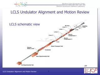
Interference Alignment By Motion
Interference Alignment By Motion. Swarun Kumar. Fadel Adib , Omid Aryan, Shyamnath Gollakota and Dina Katabi . Major Advances in MIMO. E.g. Interference Alignment Significant gains in throughput. Single-Antenna Devices. Single Antennas, due to limits on power and size

Interference Alignment By Motion
E N D
Presentation Transcript
Interference Alignment By Motion Swarun Kumar FadelAdib, Omid Aryan, ShyamnathGollakotaand Dina Katabi
Major Advances in MIMO E.g. Interference Alignment Significant gains in throughput
Single-Antenna Devices • Single Antennas, due to limits on power and size • Largely left out of these MIMO benefits
Goal Bring MIMO Benefits to Single Antenna Devices “Interference Alignment”
Interference Alignment 2-antenna node can decode only 2 signals antenna 2 C1 C3 C2 AP 1 antenna 1 1 2 interfere interfere C1 C2 C3
Interference Alignment 2-antenna node can decode only 2 signals antenna 2 C1 C3 C2 AP 1 antenna 1 1 2 interfere interfere C1 C2 C3
Interference Alignment 2-antenna node can decode only 2 signals antenna 2 C1 C3 C2 AP 1 antenna 1 1 2 interfere interfere C1 C2 C3 “align”
Interference Alignment 2-antenna node can decode only 2 signals antenna 2 C1 C2 AP 1 antenna 1 C3 1 2 interfere interfere C1 C2 C3 “align”
Interference Alignment 2-antenna node can decode only 2 signals antenna 2 C1 one unwanted interferer AP 1 antenna 1 1 2 interfere interfere C1 C2 C3 “align”
Single-Antenna Devices Can we still perform interference alignment? Signals from all clients will change antenna 2 C1 C3 C2 AP 1 antenna 1 1 2 interfere interfere C1 C2 C3
Single-Antenna Devices Can we still perform interference alignment? Signals from all clients will change C1 antenna 2 C2 AP 1 C3 antenna 1 1 2 interfere interfere • Perform Interference Alignment purely at the AP • Eliminates feedback/cooperation with clients • Brings benefits of alignment to new devices C1 C2 C3
MoMIMO • Moves the AP’s antenna to positions that achieve interference alignment • Needs to only displace antenna by up to 2 inches • Achieves 1.98x gain in throughput over 802.11n
1. How do we “find” positions of alignment? 2. How does it impact general wireless networks?
Feasibility of “Alignment by Motion” Record antenna displacement for interference to drop below noise 1 2 AP 1 2 inch radius desired interfere C1 C2 C3
Feasibility of “Alignment by Motion” 90th Percentile: 1 inch Median: 0.3 inch • Why is the required displacement small?
A Simple Example AP 1 1 2 Reference align Reference C1 C1 antenna 2 antenna 1
A Simple Example AP 1 1 antenna 2 2 C1 Reference align Reference C1 • Goal: Minimize signal from C1 to antenna 2 0 antenna 1
Indoor Environments Rich in Multipath High signal @2 (poor alignment) • Paths combine constructively or destructively based on phase AP 1 1 2 C1
Indoor Environments Rich in Multipath • Paths combine constructively or destructively based on phase • For Wi-Fi, 2” ≈ λ/2 AP 1 1 2 λ 0° 360° C1 Paths differ by extra 2”
Indoor Environments Rich in Multipath • Small displacement suffices for alignment • Generalizes to many reflectors, any alignment Low Signal @2 (good alignment) • Paths combine constructively or destructively based on phase • For Wi-Fi, 2” ≈ λ/2 • In-phase paths now out-of-phase! AP 1 1 2 λ 180° 0° 2 C1 Paths differ by extra 2”
How Can We Find Good Alignment? We must quantify goodness of alignment • Goal: Find antenna location that minimizes interference C1 antenna 2 Poor C1 { C2 interference C2 Good { antenna 1 interference C1 C2 interference ≈ 0
Naïve solution: Random walk Does not work! • Simulated the spatial profile of interference • Ten reflectors placed in randomly chosen locations • Applied standard multipath models
Naïve solution: Random walk High interference 30 3 20 2 Interference(dB) 10 1 y (in) 0 0 -1 -10 -2 -3 3 -1 0 2 -2 1 -3 x (in)
Naïve solution: Random walk Goal: Find blue spots Low interference 3 30 2 20 1 Interference(dB) 0 10 -1 y (in) 0 -2 -10 -3 3 -1 0 2 -2 1 -3 x (in)
Naïve solution: Random walk Goal: Find blue spots Blue spots of low interference are small Hard to stumble upon in a random walk 3 30 2 20 1 0 10 Interference(dB) -1 y (in) 0 -2 -10 -3 3 -1 0 2 -2 1 -3 x (in)
Key Observation: Interferenceis smooth • Wireless channels are continuous and smooth functions over space 3 30 2 20 1 Interference(dB) y (in) 0 10 -1 0 -2 -10 -3 3 -1 0 2 -2 1 -3 x (in)
Solution: A Hill Climbing Algorithm • Move in random direction and track interference 3 30 2 20 1 Interference(dB) y (in) 0 10 -1 0 -2 -10 -3 3 -1 0 2 -2 1 -3 x (in)
Solution: A Hill Climbing Algorithm • Move in random direction and track interference • If interference : continue in that direction 3 30 2 20 1 Interference(dB) y (in) 0 10 -1 0 -2 -10 -3 3 -1 0 2 -2 1 -3 x (in)
Solution: A Hill Climbing Algorithm • Move in random direction and track interference • If interference : continue in that direction 3 30 2 20 1 Interference(dB) y (in) 0 10 -1 0 -2 -10 -3 3 -1 0 2 -2 1 -3 x (in)
Solution: A Hill Climbing Algorithm • Move in random direction and track interference • If interference : continue in that direction • If interference : continue in opposite direction 3 30 2 20 1 Interference(dB) y (in) 0 10 -1 • Algorithm converges to spot of minimum interference • Guides antenna to find positions of alignment 0 -2 -10 -3 3 -1 0 2 -2 1 -3 x (in)
1. How do we “find” positions of alignment? 2. How does it impact general wireless networks?
Interference Alignment Align C2 and C3 AP 1 AP 2 AP 3 C1 C2 C3
Interference Alignment Align C1 and C3 AP 1 AP 2 AP 3 C1 C2 C3
Interference Alignment Align C1 and C2 AP 1 AP 2 AP 3 C1 C2 C3
Interference Alignment AP 1 AP 2 AP 3 C1 C2 C3 • 3 concurrent streams Gain in throughput! • N antenna APs enable N+1 concurrent uplink streams
What about downlink traffic? AP 1 AP 2 AP 3 C1 C2 C3
What about downlink traffic? AP 1 C2 C3
AP 1 has 2 antennas 2 antenna node can null interference at up to 1 antenna C2 & C3 aligned at AP 1 AP 1 null ?? C2 C3 Nothing!
AP 1 has 2 antennas 2 antenna node can null interference at up to 1 antenna C2 & C3 aligned at AP 1 AP 1 null for free! null C2 C3
Uplink Wireless Channels (h1, h2) (h3, h4) antenna 2 AP 1 antenna 1 h1 h4 h3 h2 C3 C2 h1 h2 h3 h4 =
Downlink Wireless Channels Channel Reciprocity x αx AP 1 null h1 h4 h3 h2 C3 C2 h1x + h2αx
Downlink Wireless Channels Channel Reciprocity x αx AP 1 null h1 h4 h3 h2 C3 C2 h1x + h2αx = 0
Downlink Wireless Channels • Alignment on the uplink enables nulling on the downlink, with no extra movement Channel Reciprocity x αx AP 1 null null h1 h4 h3 h2 C3 C2 -h1 h2 -h3 h4 h1 h2 h3 h4 α= α= =
Downlink Traffic AP 1 AP 2 AP 3 C1 C2 C3
Downlink Traffic AP 1 AP 2 AP 3 C1 C2 C3
Downlink Traffic AP 1 AP 2 AP 3 C1 C2 C3
Downlink Traffic AP 1 AP 2 AP 3 C1 C2 C3 • 3 concurrent streams on the downlink • MoMIMO provides gains to uplink & downlink traffic
MoMIMO Implementation • Implemented on USRP N210 • Mounted antenna on Roomba to emulate sliding antennas • Compare MoMIMO with 802.11n, n+