MODULE 9 – CONTROL SYSTEMS: MICROPROCESSOR CONTROL
MODULE 9 – CONTROL SYSTEMS: MICROPROCESSOR CONTROL. Goal. This module is to provide an introduction to microprocessor control systems and how they can be used for ROV control. The MATE ROV Control System is used as a reference. Objectives.

MODULE 9 – CONTROL SYSTEMS: MICROPROCESSOR CONTROL
E N D
Presentation Transcript
Goal • This module is to provide an introduction to microprocessor control systems and how they can be used for ROV control. The MATE ROV Control System is used as a reference.
Objectives • Upon completion of this module, the student should be able to: • Identify the main components of a microprocessor system • Describe binary signaling levels representative of a binary 0 and binary 1 • Connect the Arduino controller to a laptop and download software • Use sample programs for basic interfacing
Sections • Microprocessor Control Systems • Microprocessors • Input/Output Devices • Communication • The Arduino Uno Board • EEPROM • RAM • Programmable Input/Output pins • Analog Input pins • USB connection
References • “Underwater Robotics Science, Design & Fabrication”, Chapter 9
Objective 1: • Identify the main components of a microprocessor system
Definitions • Input Device: • An input device provides data and control signals to a computer • On an ROV, input devices may include: • Joystick (input from human operator) • Keyboard (input from a human operator) • Voltage/current sensors (inputs regarding system health) • Underwater camera • Depth sensor • Heading sensor • Pitch/roll sensor • Leak detector • Temperature sensor • And many more depending on the application
Definitions (cont’d) • Output Device: • An output device is used to communicate the results of a process into human observable form. • On an ROV, output devices may include: • Video display • Thruster speed/direction • Tool actuation • Lighting control
Definitions (cont’d) • Control System: • A control system regulates outputs based upon a set of inputs and an established control protocol. • On an ROV, the control system is comprised of inputs, outputs as indicated above, one or more computers, and of course, one or more human operators
Computers in ROVs • Industrial ROVs rely on one or more computers for control • The computers may be either on board the ROV, at the surface, or distributed • Computers may include the desktop or notebook type that we use regularly but will also likely include one or more embedded controllers
Embedded Controller • An Embedded Controller incorporates all of the components of a microprocessor system on a single integrated circuit (chip). These components include: • Microprocessor • Memory • Input/Output • Pins that receive inputs from other system devices • Pins that provide outputs to other system devices • Now, consider the function of each of these components
Microprocessor • This is the brain of an embedded controller. It is responsible for: • Controlling the flow and timing of the computer program • Performing all arithmetic and logic operations • Exchanging information with the memory and input/output devices
Memory • Embedded controllers use two types of memory: • EEPROM (Electrically Erasable Programmable Read Only Memory) is non-volatile memory. That is, the information remains even through a power-down. • RAM (Random Access Memory) is volatile memory. That is, the information is lost when the controller loses power.
Memory (cont’d) • Note that the main difference between EEPROM and RAM is volatility. If information has to be available next time you power up, such as the program, it must be stored in EEPROM. • Why bother with RAM since we can write to EEPROM? • It is faster to write to RAM and computers are prized for their speed.
Input/Output • The embedded controller uses dedicated pins to communicate with the input and output devices • The input pins receive signals from the human operator and sensors on the ROV • The output pins send signals to the human operator and control the thrusters and tools on the ROV
Objective 2: • Describe binary signaling levels representative of a binary 0 and binary 1
Information Representation • Reference Chapter 9, section 5.3 – 5.8
Information Representation • Computers represent information as a pattern of 1s and 0s. Computerelectronics are only stable in one of two states. Hence, they are binary (bi=two) systems. • Conventionally, a high voltage (usually 5V) is a 1 and a low voltage (usually 0V) is a 0. • Numbers, letters, video, audio, temperature, depth, etc. can be represented in binary format.
Information Communication • Each input/output pin will either be 5V (high or 1) or 0V (low or 0) at any point in time • Data may be exchanged with the outside world in parallel using multiple pins to represent a value. • However, due to the limited number of pins, on an Embedded Controller, data is more likely to be exchanged with the outside world serially by sending a series of 1s and 0s on a single pin. • Communication is only successful when both the sender and receiver agree on the coding protocol in terms of voltages and data rates.
Information Communication (cont’d) • There are many standard data communication protocols including: • RS-232 • RS-485 • I²C • Ethernet • USB • These examples all happen to be serial protocols • An embedded controller can communicate using any of these methods using appropriate interfaces and software
Embedded Controller Options • There are many embedded controller options available including: • PIC • ARM • ATMEL • All will be similar in concept but will vary based upon: • Speed • Memory capacity • Instruction set • I/O capacity
Objective 3: • Connect the Arduino controller to a laptop and download software
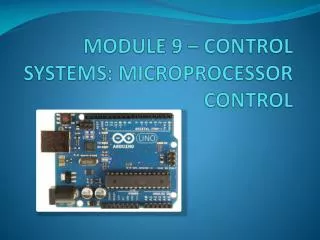
The Arduino Uno Board • This course uses the Arduino Uno, which incorporates the ATmega328 microcontroller • This board has the following features • 14 digital input/output pins (of which 6 can be used as PWM outputs - more on PWM later), • 6 analog inputs, • a 16 MHz crystal oscillator, • a USB connection • 32kB flash program memory • 1kB EEPROM • 2kB RAM • Additional details may be found at www.arduino.cc
The Arduino Uno Board 14 Digital Input/Output (6PWM) Reset USB Microcontroller 16 MHz crystal Power 7-12V 6 Analog Input
Arduino Development Environment • The Arduino development environment contains: • A text editor for writing program code, (referred to as a sketch by Arduino) • A message area, • A text console, • A toolbar with buttons for common functions, • A series of menus. • The Development Environment connects to the Arduino hardware to upload programs and communicate with them. • Additional details may be found at http://arduino.cc/en/Guide/Environment
Installing Arduino Software • Ensure that the Arduino software is installed before proceeding • See procedure in Module 3 for downloading and installing Arduino software
Connecting the Hardware • Plug your Arduino into a USB port on your computer • Note the green light indicating that it is powered up • The Arduino will start running the program (sketch) in memory each time it powers up or is reset (the red button)
Running the Arduino Development Environment • Now let’s try it out! • Navigate to your Arduino folder • Run the Arduino application • A text box window opens • You write sketches in the text box Write your program here
Running the Arduino Development Environment • Go to http://arduino.cc/en/Guide/Environmentto read a description of the controls in the Development Environment • As you MouseOver each control, it is identified on the Development Environment panel • Check your Device Manager to determine the Arduino com: port. Ensure that your software finds the Arduino board on the right serial com: port by selecting the appropriate one from the Tools|Serial Port menu item
Arduino Programming • The standard Development Environment uses the C programming language. If you are not familiar with C, you can find many tutorials online with a Google search or you may elect to learn as you work your way through the examples provided on the Arduino web site. • A description of the Arduino C language implementation may be found at http://arduino.cc/en/Reference/HomePage
Arduino Programming • Some things to watch for when programming in C • C is case sensitive so a variable called “Depth” is not the same as one called “depth” • Lines end with a semicolon • = assigns a value to a variable while == is a test to determine if two things are equal (don’t mix them up since they behave differently) • // comments a single line • /* comments everything following until a */ is reached • Blocks of program code are enclosed by braces { }
YouTube Arduino Tutorials • Jeremy Blum has an excellent tutorial series on the Artuino on YouTube • Watch the first one now at Jeremy Blum’s Arduino Tutorial 1
Objective 4: • Use sample programs for basic interfacing
Sample Arduino Sketches (BareMinimum) • Go to http://arduino.cc/en/Tutorial/HomePage and examine the “BareMinimum” sketch • Note that every sketch will consist of a Setup function that runs once at the beginning • This is followed by a Loop function that will repeat forever • These functions do not return a value, hence are void • Load the BareMinimumsketch from the examples|01.Basics folder • Upload the sketch to run it (No output expected)
Sample Arduino Sketches (Blink) • Go to http://arduino.cc/en/Tutorial/HomePage, read the background and examine the “Blink” sketch • Load the Blink sketch from the examples|01.Basics folder
/* Blink Turns on an LED on for one second, then off for one second, repeatedly. This example code is in the public domain. */ // Pin 13 has an LED connected on most Arduino boards. // give it a name: int led = 13; // the setup routine runs once when you press reset: void setup() { // initialize the digital pin as an output. pinMode(led, OUTPUT); } // the loop routine runs over and over again forever: void loop() { digitalWrite(led, HIGH); // turn the LED on (HIGH is the voltage level) delay(1000); // wait for a second digitalWrite(led, LOW); // turn the LED off by making the voltage LOW delay(1000); // wait for a second }
Sample Arduino Sketches (Blink) • Upload the sketch to run it • Observe that the LED is on for 1 second then off for 1 second • This is a digital output since the value is only high or low. There is no intermediate voltage.
Test Your Knowledge (Blink) • Change your sketch to make the LED stay on for 5 seconds then go off for 5 seconds • Upload your revised program to the Arduino • Use a voltmeter to measure between the output pin (13) and GND. You should see the DC voltage vary between 0 and 5V • Change your sketch to make the LED turn on for 50ms and then off for 50ms • Observe the LED blinking faster • Now what is the output voltage reading? Why? • Is this still a digital output?
Test Your Knowledge (Blink) (cont’d) • The voltmeter averages its reading over a longer time than the blink rate so you should read about 2.5V since the LED is on for half of the time. It is still a digital output, as could be shown on an oscilloscope. • Change your sketch so that the LED is on for 25ms and off for 75 ms. • Is the output voltage now about 1.25V? • What voltage would you expect if the LED was on for 75ms and off for 25ms? • Prove it.
Test Your Knowledge (Blink) (cont’d) • Change your sketch so that the LED is on for 5ms and off for 5ms • What output voltage do you expect? • Is it 2.5V? • Why isn’t the LED blinking? • Your eyes cannot perceive flashing faster than about 25 times per second and the LED is flashing at 100 times per second. Research “persistence of vision” if interested in this effect. (think of movies, television, and flip books)
Test Your Knowledge (Blink) (cont’d) • Adjust your sketch for the following ON/OFF times. Record the voltage and observe the LED for each: • 1ms/9ms • 3ms/7ms • 5ms/5ms • 7ms/3ms • 9ms/1ms • Do the voltages match expectations? • How does your eye perceive the LED intensity for each combination? • Reflect on this when PWM is presented later
Sample Arduino Sketches (DigitalReadSerial) • Go to http://arduino.cc/en/Tutorial/HomePage, read the background and examine the “DigitalReadSerial” sketch • Set up the switch input with a pulldown resistor on pin 2 as illustrated • Load the DigitalReadSerialsketch from the examples|01.Basics folder
/* DigitalReadSerial Reads a digital input on pin 2, prints the result to the serial monitor This example code is in the public domain. */ // digital pin 2 has a pushbutton attached to it. Give it a name: intpushButton = 2; // the setup routine runs once when you press reset: void setup() { // initialize serial communication at 9600 bits per second: Serial.begin(9600); // make the pushbutton's pin an input: pinMode(pushButton, INPUT); } // the loop routine runs over and over again forever: void loop() { // read the input pin: intbuttonState = digitalRead(pushButton); // print out the state of the button: Serial.println(buttonState); delay(1); // delay in between reads for stability }
Sample Arduino Sketches (DigitalReadSerial) • Run the sketch (don’t forget to enable the serial monitor in the development environment) • What do you observe as you turn the switch on and off?
Test Your Knowledge (DigitalReadSerial) • Modify your sketch so that the pin 13 LED turns on when the switch is closed and off when the switch is open • Test it • Modify your sketch so that the pin 13 LED turns off when the switch is closed and on when the switch is open • Test it
FurtherReinforcement • Watch Jeremy Blum’s tutorial 2 at Jeremy Blum’s Arduino Tutorial 2 • Note the discussion on switch debounce • If you need a refresher on basic Electrical Engineering, watch tutorial 3 at Jeremy Blum’s Arduino Tutorial 3