Download
1 / 45
450 likes | 469 Vues
Explore opportunities and challenges in deploying wireless DSL cost-effectively with meshed ATM architecture. Compare wireless coverage models, discuss performance measures for base stations, QoS delivery methods, backhaul requirements, and proposed wireless models.

E N D
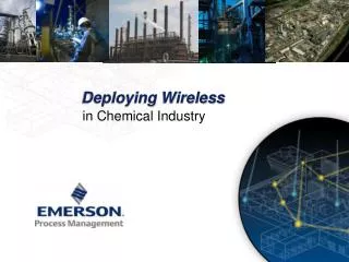
Deploying Wireless DSL Cost Effectively with Meshed ATM Architecture Frank W. Massa - Wireless, Inc. Broadband Wireless World Forum
Goals • Review the broadband wireless access opportunity • Explore the two basic wireless coverage models • Discuss performance measures for wireless base stations • Discuss system growth issues • Compare ATM and IP as methods for delivering QoS and mixed services and for improving reliability • Discuss backhaul requirements and propose a wireless backhaul model
The Opportunity • DSL ‘Homes Passed’ estimated to be 30 - 50% • at 512 kbps or more • 1 - 6 Mbps desired • Even ‘Covered Areas’ may not offer complete coverage • Cable, Satellite services have comparable limitations San Francisco Bay Area DSL coverage (green), from DSL Reportshttp://dslreports.com/shownews/373
Spot or Cellular Coverage? • Spot Coverage requires only a single central base station • Line of sight requirements • Limits on range • can be quite limited at high frequencies • Obstruction limits • no choice of serving base station • Maximum usable bandwidth Denver Area Coverage - Sprint Broadband Direct (sm)http://www.sprintbroadband.com/availability/index.pl
Wireless “Total System” Solution • Wireless Broadband “First Mile” Access • Wireless Transport, Backhaul and Switching Solutions • Network Management Solution • Megabit plus per second data rates for SOHO and residential markets • Toll grade voice services (QoS) • Integrated End-to-End solution
Broadband Core Network Leased Line Pt-Mp Access Pt Switch Backhaul NMS Total System Solution
Least Cost Long Distance Voice Gateway PSTN Wireless DSL Access Network Class 5 Switch Internet $ Corporate Subscriber Management System Backbone Network Content Services Into the Core Network Edge Switch
Total Solution Key Requirements • Pt-Mp waveform • Superior capacity in multi-cell deployment • Superior range for given throughput • Allows operation in any single (TDD) contiguous or FDD bands • Advanced multipath mitigation • High-order signal processing for excellent performance in non-LOS signal paths and areas with reflections and dense RF overlap • Integrated Customer Premise Equipment • Avoids expensive CPE installation • Low - cost solution which includes antenna, RF, Telephony and Data • Network architecture • Allows QoS for voice and other low latency applications • Efficient multiplexing and switching • Ready integration with DSL-based network infrastructure
Key Features and Benefits (Cont) • Efficient Multiple Access Control protocol • True bandwidth-on-demand • Demand assignment approach avoids inefficiencies of contention-based approaches • High throughput maintained with heavy loading • Throughput per user similar to xDSL • Plain Old Telephony Service • Support interfaces to industry leading DSL Voice Gateway providers • Integrated access - data and voice in one CPE
License-Free 2.4 GHz ISM 5.3 GHz UNII 5.8 GHz UNII 5.8 GHz ISM License 700 MHz UHF PCS (1.9 GHz) MDS/MMDS (2.1/2.6) WCS (2.3 GHz) 3.5 GHz (3.4 - 4.2 GHz) ETSI ITU Industry Canada Pt-Mp Frequencies (Below 6 GHz)
Multipath DSSS Code Division Multiple Access
1 1 1 1 1 1 1 1 1 1 1 1 2 1 2 1 1 1 4 4 1 1 5 5 1 1 1 1 2 2 1 1 1 4 4 1 1 1 5 5 1 1 1 3 6 1 1 1 3 1 1 1 1 1 1 6 9 3 12 6 3 9 12 6 7 8 10 11 7 8 10 11 TDMA (N = 4, Sectored) CDMA (N = 1, Sectored) CDMA Spectral Efficiency
Up Stream Remotes transmit to AP sectors (as needed) Down Stream AP Sectors transmit to remotes Time Division Duplex (TDD)
Frequency Division Duplex (FDD) Up Stream and Down Stream - AP sectors transmit and receive to remotes simultaneously - Requires separate transmit and receive bands
1V 3V 8H 2H 1V 3V 8H 2H 7V 5V 6H 4H 7V 5V 6H 4H 1H 3H 2V 8V 1H 3H 2V 8V 7H 5H 4V 6V 7H 5H 4V 6V 1V 3V 8H 2H 1V 3V 8H 2H 7V 5V 6H 4H 7V 5V 6H 4H 1H 3H 2V 8V 1H 3H 2V 8V 7H 5H 4V 6V 7H 5H 4V 6V Cellular Deployment • Significant increase in system capacity • Tradeoff: per cell capacity • TDMA or FDMA: channels • CDMA: codes • Cell size is a new deployment parameter
Burst Rate and User Capacity • OPNET ‘Heavy HTML’ Model • Web browsing • Email • FTP • DSL at 256 kbps downstream • 1 user • Wireless aggregated at 1.8 Mbps downstream • 60 users
Download Rates Download Performance vs. Number of Active Users per Sector 1400 3.6 Mbps Sector 1200 1000 1 Mbps DSL 800 Average Per-User Download 1.8 Mbps Sector Burst Rate (Kbps) 600 400 256 kbps DSL 200 0 0 20 40 60 80 100 Number of Active Users
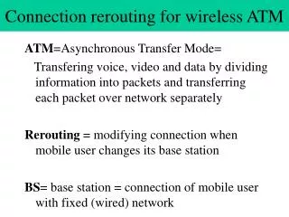
Quality of Service • Why QoS? • Critical for public shared services • Allows for different SLAs • Support for mixed services • Protocols • ATM provides rich, mature set of QoS mechanisms • Switching protocols just beginning to be implemented • IP has emerging QoS mechanisms • IP has mature routing protocols • Importance of the MAC
Non-Line of Sight Range Rappaport from "Measurements and Model for Radio Path Loss and Penetration Loss In and Around Homes and Trees at 5.85 GHz.", IEEE TRANS COMM, V 41, N 11, Nov. 1998.
Range vs. Capacity Balance • Model based on 1.9 GHz, 10 MHz BW, radio design Bandwidth Efficiency
Neighborhood Deployment • Small • Entirely outdoor • Mounted on existing structures • Rooftops • Power poles • Light poles • Modest coverage area • Modest cost
Pt-MP Access Point • Integrated package for low profile deployment • Modularity supports single sector or sectorized deployment (Omni, 3-sector or 6-sector). • “Master” and “Slave” Configurations • Master includes Integrated switch functions and timing (GPS) • Standard WAN interfaces for wireless backhaul • Integral network management
Integrated Switching • Multiplexing and switching functions • Carrier class features with lower cost per port • Switching fabric up to 622 Mb/s • Designed for all-outdoor, full-temperature operation • Small size and weight, low power consumption, “hardened” • Implements mesh network • Moving network intelligence into the local loop • Route and equipment redundancy - all elements can be non-redundant • QOS, traffic prioritization • QOS Billing options (platinum/gold/silver SLA) • Dynamic load balancing • Opportunity for local caching of bandwidth intensive data
Outdoor CPE • Outdoor antenna and RF; connects to indoor IAD over existing twisted pair • Indoor access not required for installation • 10BaseT for data and RJ-11 for voice • Requires LOS or Near - LOS
Voice over IP or ATM Laptop computer Existing indoor telephone wiring To Wireless Access Point Wireless IAD Ethernet Desktop PC ODU CPE & Antenna Coexistence with other optional Home Networking products Telephone Line Analog Voice Analog Telephone Outdoor Telephone Junction box (NID) Voice + Data Outdoor CPE with Indoor IAD Outdoor Indoor
Indoor CPE Indoor desktop version • Fully integrated access device, including antenna and RF front end • Easy installation maximizes potential subscriber base • 10BaseT for data and RJ-11 for voice • For freq < 3 GHz
Outdoor Analog Telephone Existing indoor telephone wiring To Wireless Access Point Desktop PC Wireless IAD & Antenna Ethernet HPNA Telephone Line Analog Voice Laptop computer Outdoor Telephone Junction box (NID) VoATM using AAL2 Indoor Indoor CPE
Backhaul Options • Wired • Availability • Recurring cost • Time to deployment • Licensed wireless • Shorter time to deployment • Spectrum availability • Unlicensed wireless • Shortest time to deployment • No recourse for interference
POP POP Mesh Redundant Wireless Backhaul • Ring or Mesh Architecture • Provide multiple paths of egress • Self-healing nature • Provides load balancing in network • Can be designed for incremental cost over minimal star network • Requires switching or routing at node points
Backhaul Network Supports Growth High growth area POP POP
Meshed Backhaul in Action • Mesh laid out for line-of-sight • Connections may include doglegs for line-of sight Point to Point RadioRelay Point Wireless Access Point& Switch 1 Mi. USGS Photo: Denver Suburb.
Wireless Relay • Field trail element • Two back-to-back radios • Light pole mounted
Integrating the Pieces • Voice and data traffic • Integration with wired access methods Backhaul Radios Access Point EdgeSwitch Outdoor CPE To PSTN VoiceGateway Class 5Switch Hardened Switch To Internet IAD SubscriberManagementSystem Customer Premises NSP Point of Presence
Conclusions • Wireless broadband system engineering has multiple facets • Coverage • Capacity • Integrated services with QOS • Costs • A small cell, low footprint design is achievable • Wireless backhaul • Self healing mesh networks • Rapid system deployment