Download
1 / 1
10 likes | 190 Vues
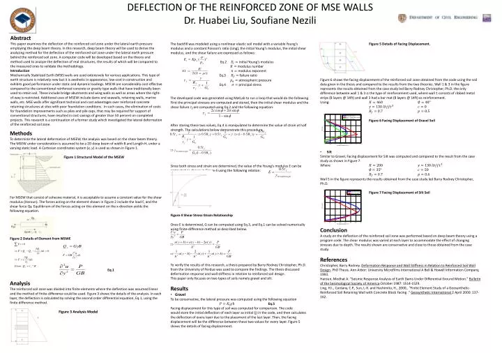
DEFLECTION OF THE REINFORCED ZONE OF MSE WALLS Dr. Huabei Liu, Soufiane Nezili. Abstract

E N D
DEFLECTION OF THE REINFORCED ZONE OF MSE WALLS Dr. Huabei Liu, SoufianeNezili Abstract This paper examines the deflection of the reinforced soil zone under the lateral earth pressure employing the deep beam theory. In this research, deep beam theory will be used to derive the analyzing method for the deflection of the reinforced soil zone under the lateral earth pressure behind the reinforced soil zone. A computer code will be developed based on the theory and method used to analyze the deflection of real structures, the results of which will be compared to the measured ones to validate the methodology. Introduction Mechanically Stabilized Earth (MSE) walls are used extensively for various applications. This type of earth structure is relatively new but it is aesthetic in appearance, low-cost in construction and exhibits good performance under static and dynamic loadings. MSEW are considerably cost-effective compared to the conventional reinforced concrete or gravity type walls that have traditionally been used to retain soil. These include bridge abutments and wing walls as well as areas where the right-of-way is restricted. Additional uses of MSEW include dams and seawalls, retaining walls, marine walls, etc. MSE walls offer significant technical and cost advantages over reinforced concrete retaining structures at sites with poor foundation conditions. In such cases, the elimination of costs for foundation improvements such as piles and pile caps, that may be required for support of conventional structures, have resulted in cost savings of greater than 50 percent on completed projects. This research is a continuation of a former study which investigated the lateral deformation of the reinforced soil zone. • The backfill was modeled using a nonlinear elastic soil model with a variable Young’s modulus and a constant Poisson’s ratio (Ling), the initial Young’s modulus, the initial shear modulus, and the shear failure are expressed as follows: • Eq.2 initial Young’s modulus • modulus number • modulus exponent • Eq.3 failure ratio • atmospheric pressure • Eq.4 principal stress • The developed code was generated using MatLab to run a loop that would do the following. • First the principal stresses are computed and stored, then the initial shear modulus and the shear failure are computed using Eq.2 and the following equation: • After storing these two values, Eq.4 is manipulated to determine the value of strain at half strength. The calculations below demonstrate this procedure. • Since both stress and strain are determined, the value of the Young’s modulus E can be computed as shown in Figure 4 using the following relation: • Figure 4 Shear Stress-Strain Relationship • Once E is determined, G can be computed using Eq.3, and Eq.1 can be solved numerically using finite-difference method as described below. • To verify the results of this research, a thesis prepared by Barry Rodney Christopher, Ph.D. from the University of Perdue was used to compare the findings. The thesis discussed deformation response and wall stiffness in relation to reinforced soil design. • This paper only focuses on two types of soils namely gravel and silt. • Results • Gravel • To be conservative, the lateral pressure was computed using the following equation • Eq.5 • Facing displacement for this type of soil was computed for comparison. The code would store the initial deflection of each layer as initial (j) in the code, and then calculates the deflection of every layer due to the placement of the last layer. Then, the facing displacement will be the difference between these two values for every layer. Figure 5 shows the details of facing displacement. • Figure 5 Details of Facing Displacement. • Figure 6 shows the facing displacement of the reinforced soil zone obtained from the code using the soil data given in the thesis and compared to the results from the two theories. Wall 1 & 3 in the figure represents the results obtained from the case study led Barry Rodney Christopher, Ph.D. the only difference between wall 1 & 3 is the type of reinforcement used, where wall 1 consists of ribbed metal strips (8 layers @ 14ft) and wall 3 had a bar mat (8 layers @ 14ft) as reinforcement. • Using: • Figure 6 Facing Displacement of Gravel Soil • Silt • Similar to Gravel, Facing displacement for Silt was computed and compared to the result from the case study as shown in Figure 7. • Where • Wall 5 in the figure represents the results obtained from the case study led Barry Rodney Christopher, Ph.D. • Figure 7 Facing Displacement of Silt Soil • Conclusion • A study on the deflection of the reinforced soil zone was performed based on deep beam theory using a program code. The shear modulus was varied at each layer to accommodate the effect of changing stresses due to depth. The results shown are conservative and close to those obtained from the case study. • References • Christopher, Barry Rodney. Deformation Response and Wall Stiffness in Relation to Reinforced Soil Wall Design. PhD Thesis. Ann Arbor: University Microfilms International A Bell & Howell Information Company, 1993. • Haroun, Medhat A. "Seismic Response Analysis of Earth Dams Under Differential Ground Motion." Bulletin of the Seismological Society of America October 1987: 1514-1529. • Ling, H.I., Cardany, C.P., Sun, L-X. and Hashimito, H., 2000,. "Finite Element Study of a Geosynthetic-Reinforced Soil Retaining Wall with Concrete Block Facing ." Geosynthetic International 2 April 2000: 137-162. Methods To determine the lateral deformation of MSEW, the analysis was based on the shear beam theory. The MSEW under consideration is assumed to be a 2D deep beam of width B and Length H, under a varying static load. A Cartesian coordinates system (x, y) is used as shown in Figure 1. Figure 1 Structural Model of the MSEW For MSEW that consist of cohesive material, it is acceptable to assume a constant value for the shear modulus (Haroun). The forces acting on the element shown in Figure 2 include the load F, and the shear force Qy. Equilibrium of the forces acting on this element on the x-direction yields the following equation. Figure 2 Details of Element from MSWE Eq.1 Analysis The reinforced soil zone was divided into finite elements where the deflection was assumed linear and the method of finite-difference could be used. Figure 3 shows the details of the analysis. In each layer, the deflection is calculated by solving the second order differential equation, Eq.1, using the finite difference method. Figure 3 Analysis Model