Understanding Digital Filter Design and Transfer Functions
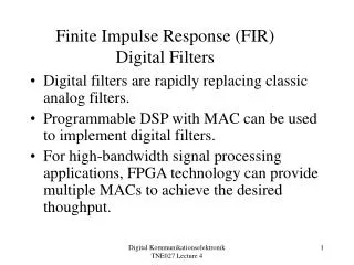
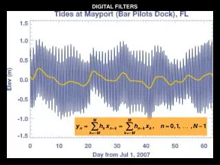
This article explores the relationship between discrete-time systems and their transfer functions, demonstrating how to derive input-output relationships. Using C++ programming, we illustrate a practical example of filtering operations in discrete time. The analysis covers impulse and step responses, and examines the frequency response to determine if the filter is a low-pass or high-pass filter. Additionally, we introduce the matched z-transform method for digital filter design, matching the impulse response of analog filters with digital counterparts to ensure desired characteristics.


Understanding Digital Filter Design and Transfer Functions
E N D
Presentation Transcript
x(t) A/D x[n] Computer y[n] D/A y(t) Example:
When we describe a discrete-time system by a discrete-time transfer function what can we find-out about the system from the transfer function?
Example: What is the input-output relationship for the following transfer function? Solution: From the definition of the transfer function we have
Cross-multiplying and converting back to discrete-time domain we have In other words, the current output is equal to one-half times the previous output plus the current input.
To get the current output y[n], which is sent to the D/A, we get the previous output y[n-1] (sent the last time to the D/A), multiply it by one-half and add to it the current input from the A/D. In a programming language like C++, the code would look something like this: yp = 0; // set “previous” y to zero while (true) { x = inp(ad); // get new sample y = 0.5*yp+x; // perform filtering operation outp(y, da); // send filtered sample to D/A yp = y; // set “current” to “previous” // for next iteration }
Now what does this operation do to an input signal? Example: find the impulse and step responses to the previous filter. Solution: we could use z-transforms or convolution to find the output when the input is an impulse or a step, but instead, let us see how the output “evolves.” A table will be created with three columns: n, x[n] and y[n]. Each column will correspond to an instance in discrete-time. For the impulse input x[n]=d[n] we have
The plots of these outputs are as follows: y[n] for x[n]=d[n] n 1 2 3 4
y[n] for x[n]=u[n] 2 1 n 1 2 3 4
The responses look like those for an RC low-pass filter. What about the frequency response for this digital filter? Is it indeed a low-pass filter? To answer this question, we go back to the meaning of z:
To find the frequency response of filters described by Laplace-domain transfer functions, we let s=jW. We do the same for z-transform transfer functions: At this point we introduce a notational convenience:
So, The values of z=ejw correspond to values on the unit circle in the z-plane. The variable w will take-on values from 0 to 2p. From the relationship w=2p(W/Ws), as w goes from 0 to 2p, W/Ws will go from 0 to 1 andW will go from 0 to Ws.
Im w Re
The range W=0 to W=Ws corresponds to the spectrum of the sampled signal through the lower half of the first alias. The significant frequencies of the signal are from W=0 to W=Ws/2. This range of frequencies corresponds to the range w=0 to w=p. Xs(W) Ws/2 -Ws Ws W w=0 w=2p w=0 to p
To find the frequency response of a digital filter, we plug-in z=ejw to the transfer function and evaluate this function for w=0 to p.
Example: Find the frequency response of the digital filter described by the transfer function Solution: We evaluate H(ejw) for w=0,p/2 and p.
Im Re
We can readily see that the frequency response corresponds to that of a low-pass filter.
A better frequency response plot would include more sample points.
Example: Find the frequency response of the digital filter described by the transfer function Solution: As before, we evaluate H(ejw) for w=0,p/2 and p.
Im Re
Notice that the frequency of maximum response corresponds to the angular location of the polex Suppose the angular location of the pole were at w=p/2. What would the frequency response be?
Im Re
The corresponding transfer function would be Evaluating this transfer function at z=ejw for w=0,p/2 and p, we have
The angular location of the poles correspond to frequencies of resonant peaks. We could improve upon the design of the previous filter by inserting zeroes at w=0 (z=1) and w=p (z= -1). The resultant transfer function would be
Im Re
We also must recognize that the poles must occur in conjugate imaginary pairs. So, The resultant frequency response has a similar shape (not quite as sharp) and has a different maximum value:
We can perform rough design digital filters in this manner by trial-and error placement of poles and zeros in the complex plane. However, more precise and analytic methods of designing digital filters exist and will be discussed in later presentations.
Digital Filter Phase Response The phase response of a digital filter can be evaluated in a similarmanner to the magnitude response. For each frequency value, evaluate ejw, and H(ejw). But instead of computing |H(ejw)|, compute H(ejw).
Example: Find the phase response of Solution: We let z=ejw, and find the angle of the complex value.
The Matched z-Transform In the matched z-transform digital filter design method we try to “match” the impulse response of the analog filter with that of the digital filter being designed. To match the impulse responses, we take the inverse Laplace transform of the analog filter H(s)h(t), then sample the impulse response h(t)h[n], then take the z-transform of the sampled impulse response to get the z-transform transfer function h[n]H(z).
Analog Prototype Digital Filter L-1 Z sample Once we have our z-transform transfer function H(z), we apply the definition of the transfer function to write our digital filter equations:
Example: Use the matched filter design method to design the digital equivalent of an integrator. Solution: The analog transfer function is The inverse Laplace transform is
We then sample the impulse response to get h[n]: Finally, we take the z-transform of the impulse response to get the digital filter transfer function.
Finally, we apply the definition of the z-transform transfer function to get the relationship between the input of the digital filter x[n] and the output of the digital filter y[n].
We see that the output is the summationof the input. Thus the digital filter accurately represents the analog filter. The digital filter does not always accurately represent the analog filter as will be seen in the next example.
Example: Use the matched filter design method to design the following transfer function: where Wc = Ws/4, and Ws is the sampling frequency. Solution: First, we find the impulse response
Then we sample the impulse response: Then we take the z-transform of the (discrete-time) impulse response: