Digital Filters & Signal Processing Basics
290 likes | 1.08k Vues
Learn about digital and analog filters, real-time signal processing, z transform, system stability, DFT, FFT, FIR and IIR filtering, with examples and implementations.

Digital Filters & Signal Processing Basics
E N D
Presentation Transcript
Digital Filters Real-time Digital Signal Processing
Filters Background: . Filters may be classified as either digital or analog. .Digital filters are implemented using a digital computer or special purpose digital hardware. . Analog filters may be classified as either passive or active and are usually implemented with R, L, and C components and operational amplifiers.
Filters Background: . An active filter is one that, along with R, L, and C components, also contains an energy source, such as that derived from an operational amplifier. . A passive filter is one that contains only R, L, and C components. It is not necessary that all three be present. L is often omitted (on purpose) from passive filter design because of the size and cost of inductors – and they also carry along an R that must be included in the design.
Passive Analog Filters Four types of filters - “Ideal” Background: lowpass highpass FC FC bandpass bandstop FCL FCH FCL FCH
Passive Analog Filters Realistic Filters: Background: lowpass highpass bandpass bandstop
Digital Signal Processing Basics • A basic DSP system is composed of: • An ADC providing digital samples of an analog input • A Digital Processing system (μP/ASIC/FPGA) • A DAC converting processed samples to analog output • Real-time signal processing: All processing operation must be complete between two consecutive samples
ADC and Sampling • An ADC performs the following: • Sampling • Quantization • Binary Coding • Sampling rate must be at least twice as much as the highest frequency component of the analog input signal
The z transform • Discrete equivalent of the Laplace transform
z-transform properties • Linear • Shift theorem • Note:
Transfer Function • z-transform of the output/z transfer of the input • Pole-zero form
System Stability • Position of the poles affects system stability • The position of zeroes does not
Problem1 • A system is described by the following equation: • y(n)=0.5x(n) + 0.2x(n-1) + 0.1y(n-1) • Plot the system’s transfer function on the z plane • Is the system stable?
The Discrete Fourier Transform (DFT) • Discrete equivalent of the continuous Fourier Transform • A mathematical procedure used to determine the harmonic, or frequency, content of a discrete signal sequence The Fast Fourier Transform (FFT) • FFT is not an approximation of the DFT, it gives precisely the same result
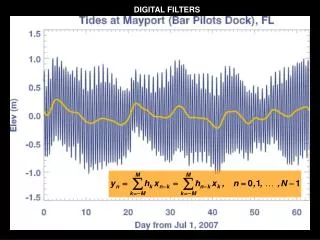
Digital Filtering • In signal processing, the function of a filter is to remove unwanted parts of the signal, such as random noise, or to extract useful parts of the signal, such as the components lying within a certain frequency range • Digital Filter: • Input: Digitized samples of analog input (requires ADC) • Components: Digital processor (PC/DSP/ASIC/FPGA) • Output: Filtered samples(requires DAC) • Applications: noise reduction, video signal enhancement, graphic equalisers
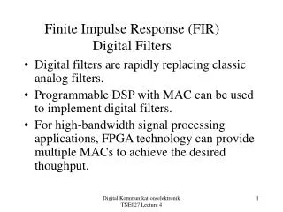
FIR filtering • Finite Impulse Response (FIR) filters use past input samples only • Example: • y(n)=0.1x(n)+0.25x(n-1)+0.2x(n-2) • Z-transform: Y(z)=0.1X(z)+0.25X(z)z^(-1)+0.2X(z)(z^-2) • Transfer function: H(z)=Y(z)/X(z)=0.1+0.25z^(-1)+0.2(z^-2) • No poles, just zeroes. FIR is stable
FIR Filter Implementation • y(n)=h(0)x(n)+h(1)x(n-1)+h(2)x(n-2)+h(3)x(n-3)
Example 2 • A filter is described by the following equation: • y(n)=0.5x(n) + 1x(n-1) + 0.5x(n-2), with initial condition y(-1) = 0 • What kind of filter is it? • Plot the filter’s transfer function on the z plane • Is the filter stable? • Plot the filter’s Implementation.
IIR Filtering • Infinite Impulse Response (IIR) filters use past outputs together with past inputs
IIR Filter Implementation • y(n)=b(0)x(n)+b(1)x(n-1)+b(2)x(n-2)+b(3)x(n-3) + a(0)y(n)+a(1)y(n-1)+a(2)y(n-2)+a(3)y(n-3)
FIR - IIR filter comparison • FIR • Simpler to design • Inherently stable • Require lower bit precision • IIR • Can simulate analog filters
Example 3 • A filter is described by the following equation: • y(n)=0.5x(n) + 0.2x(n-1) + 0.5y(n-1) + 0.2y(n-2), with initial condition y(-1)=y(-2) = 0 • What kind of filter is it? • Plot the filter’s transfer function on the z plane • Is the filter stable? • Plot the filter’s Implementation.