EE 350 / ECE 490 Analog Communication Systems
EE 350 / ECE 490 Analog Communication Systems. Ch. 1 – Introductory Topics. Syllabus. Course Objectives. Course Particulars. Textbook: Modern Electronic Communication (9 th ed.) Jeffrey S. Beasley & Gary M. Miller. Pearson / Prentice Hall. ISBN-13: 9780132251136 Required Software:

EE 350 / ECE 490 Analog Communication Systems
E N D
Presentation Transcript
EE 350 / ECE 490Analog Communication Systems Ch. 1 – Introductory Topics Fairfield U. - R. Munden - EE350
Syllabus Fairfield U. - R. Munden - EE350
Course Objectives Fairfield U. - R. Munden - EE350
Course Particulars Textbook: Modern Electronic Communication (9th ed.) Jeffrey S. Beasley & Gary M. Miller. Pearson / Prentice Hall. ISBN-13: 9780132251136 Required Software: 1.MatLab Student Ed. (The Math Works) or Classroom Kit (SOE) MatLab Tutorial by B. Aliane 2.Circuit simulator – the book uses (and should include a CD student version of) Electronics Workbench Multisim, or LTSpice IV – A useful, free spice simulation package from Linear Technologies. Web Resources: • Eidos – course materials and grades will be posted using Eidos as the course management website. http://eidos.fairfield.edu – you should have access if you are registered for the course. • Textbook Website – provides files, reviews, problems, and many resources to accompany studying with the textbook. http://wps.prenhall.com/chet_beasley_modeleccomm_9/ Performance Indicators and Grading: Three exams will be given covering several concepts each. Exams will be take-home, but individual effort. Fairfield U. - R. Munden - EE350
Academic Policies Exam grading: The purpose of the exams is to convey your understanding of the material; therefore, it is important that you show your work. Even if you feel that the solution to a problem is obvious; you must still explain why it is obvious. Furthermore; if you are asked to solve a problem using a given technique; then please use that technique; otherwise, I have no way to judge your understanding of the technique being tested. Homework policy: • Homework will be assigned from the book as your primary preparation for the exams. We will review select homework problems in class and you will be asked to work them on the board for a participation grade. We will also incorporate design problems / projects as appropriate to the material. These problems are designed to challenge you to think beyond what the book has told you, and do real engineering. There may be more than one correct answer. These will be the primary factors in your HW grade. If you know in advance that you will be missing class please contact me to make arrangemeIf you understand how to do the homework problems you will have an easier time with the Exams. Fairfield U. - R. Munden - EE350
Academic Integrity • Working with classmates to study, resolve problems, and learn the material is expected and encouraged during normal course work. However, during individual evaluations (e.g. quizzes, exams, individual projects, etc.) you are expected to comply with all standards of academic honesty. You will be graded fairly, and so your work should fairly represent your knowledge, abilities, and effort, not that of others. Any breach of integrity (including but not limited to: copying solutions, internet solutions, copying from peers, claiming work or designs without proper citation, etc.), will not only impact your ability to learn the material and my ability to help you through proper feedback, it will result in academic penalty. Any individual found in breach of this code will fail the afflicted assignment and will be asked to meet privately; any other offenses will be referred to the Dean for further action, and could result in penalties as severe as expulsion from the University. Fairfield U. - R. Munden - EE350
Schedule Fairfield U. - R. Munden - EE350
Outline • Introduction • The dB in Communications • Noise • Noise Designation and Calculation • Noise Measurement • Information and Bandwidth • LC Circuits • Oscillators • Troubleshooting Fairfield U. - R. Munden - EE350
Objectives • Describe a basic communication system and explain the concept of modulation • Develop an understanding of the use of the decibel (dB) in communication systems • Define electrical noise and explain its effect at the first stages of a receiver • Calculate the thermal noise generated by a resistor • Calculate the signal-to-noise ratio and noise figure for an amplifier • Describe several techniques for making noise measurements • Explain the relationship among information, bandwidth, and time of transmission • Analyze nonsinusoidal repetitive waveforms via Fourier Analysis • Analyze the operation of various RLC circuits • Describe the operation of common LC and crystal oscillators Fairfield U. - R. Munden - EE350
Modulation Fairfield U. - R. Munden - EE350
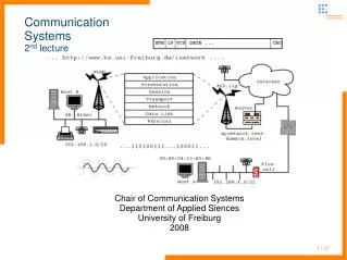
Communication Systems Figure 1-1 A communication system block diagram. Fairfield U. - R. Munden - EE350
The dB in Communications 0-dBm is measured relative to a standard of 1mW on a 600 Ω load. Other loads such as 75 Ω (video) or 50 Ω (radio) can also be denoted as dBm(75/50/600) showing the reference load and denoting 1mW of power. Fairfield U. - R. Munden - EE350
Noise • External Noise: • Human-made noise up to about 500 MHz • Atmospheric Noise: up to about 20 MHz • Space Noise (Solar and Cosmic): 8MHz to 1.5 GHz • Intrinsic Noise: • Thermal Noise (Johnson or White noise) • Shot Noise • 1/f (flicker or pink) noise • Transit Time noise Fairfield U. - R. Munden - EE350
Noise Amplification Figure 1-2 Noise effect on a receiver s first and second amplifier stages. Fairfield U. - R. Munden - EE350
Figure 1-3 Resistance noise generator. Fairfield U. - R. Munden - EE350
Noise spectrum Figure 1-4 Device noise versus frequency. Fairfield U. - R. Munden - EE350
Noise Designation • Signal to Noise Ratio • Noise Figure Fairfield U. - R. Munden - EE350
Noise Figure Spectrum Figure 1-5NF versus frequency for a 2N4957 transistor. (Courtesy of Motorola Semiconductor Products, Inc.) Fairfield U. - R. Munden - EE350
Noise Contours Figure 1-6Noise contours for a 2N4957 transistor. (Courtesy of Motorola Semiconductor Products, Inc.) Fairfield U. - R. Munden - EE350
Noise Effects • Reactance noise bandwidth typically larger than BW • Noise of First Stage in Cascaded amplifier dominates by Friiss’s Formula • Equivalent Noise Temperature Teq = To(NR-1) • SINAD used for total degradation of receivers Fairfield U. - R. Munden - EE350
Noise Measurement Figure 1-7Scope display of the same noise signal at two different intensity settings. (Courtesy of Electronic Design.) Fairfield U. - R. Munden - EE350
Figure 1-8 (a) With the tangential method, the noise signal is connected to both channels of a dual-channel scope used in the alternate-sweep mode. (b) The offset voltage is adjusted until the traces just merge. (c) The noise signal is then removed. The difference in the noise-free traces is twice the rms noise voltage. (d, e, f) This is repeated at a different intensity to show that the method is independent of intensity. Scope settings are: horizontal = 500 ms/cm, vertical = 20 mV/cm. (Courtesy of Electronic Design.) Fairfield U. - R. Munden - EE350
Fourier Analysis Figure 1-9 (a) Fundamental frequency (sin t); (b) the addition of the first and third harmonics (sint + 1/3sin 3t); (c) the addition of the first, third, and fifth harmonics (sin t + 1/3 sin 3t + 1/5 sin 5t). Square wave construction Fairfield U. - R. Munden - EE350
Fourier Analysis Figure1-10 Square waves containing: (a) 13 harmonics; (b) 51 harmonics. Higher harmonics in square wave Fairfield U. - R. Munden - EE350
Measuring Frequency Spectra Figure 1-11 (a) A 1-kHz sinusoid and its FFT representation; (b) a 2-kHz sinusoid and its FFT representation. Fairfield U. - R. Munden - EE350
Figure 1-11 (continued) (a) A 1-kHz sinusoid and its FFT representation; (b) a 2-kHz sinusoid and its FFT representation. Fairfield U. - R. Munden - EE350
Figure 1-12 A 1-kHz square wave and its FFT representation. Fairfield U. - R. Munden - EE350
Figure 1-13 (a) A low-pass filter simulating a bandwidth-limited communications channel; (b) the resulting time series and FFT waveforms after passing through the low-pass filter. Fairfield U. - R. Munden - EE350
RLC Circuits Figure 1-14 Series RLC circuit. Fairfield U. - R. Munden - EE350
Resonance Figure 1-15 Series RLC circuit effects. Fairfield U. - R. Munden - EE350
Series LC Bandpass Filter Figure 1-16 (a) LCbandpass filter and (b) response. Fairfield U. - R. Munden - EE350
Parallel LC Bandpass Figure 1-18 Parallel LC circuit and response. Fairfield U. - R. Munden - EE350
LC Filters • Filters can be designed using multiples poles • Butterworth • Chebyshev • Cauer (elliptical) • Bessel (Thomson) Fairfield U. - R. Munden - EE350
High Frequency Effects Figure 1-19 Inductor at high frequencies. Fairfield U. - R. Munden - EE350
Figure 1-20 Resistor at high frequencies. Fairfield U. - R. Munden - EE350
LC Oscillator Figure 1-21 Tank circuit flywheel effect. • Barkhausen Criteria • The loop gain must be 1 or greater • The loop phase shift must be zero degrees Fairfield U. - R. Munden - EE350
Simplified Hartley oscillator. Fairfield U. - R. Munden - EE350
Figure 1-23 Practical Hartley oscillator. Fairfield U. - R. Munden - EE350
Figure 1-24Colpitts oscillator. Fairfield U. - R. Munden - EE350
Figure 1-25 Clapp oscillator. Fairfield U. - R. Munden - EE350
Figure 1-26 Electrical equivalent circuit of a crystal. Fairfield U. - R. Munden - EE350
Figure 1-27 Pierce oscillator. Fairfield U. - R. Munden - EE350
Figure 1-28IC crystal oscillator. Fairfield U. - R. Munden - EE350
Figure 1-29 Crystal test circuit. Fairfield U. - R. Munden - EE350
Figure 1-30 Signal injection. Fairfield U. - R. Munden - EE350
Figure 1-31 Signal tracing. Fairfield U. - R. Munden - EE350
Figure 1-32 Crystal test. Fairfield U. - R. Munden - EE350
Figure 1-33 Clapp oscillator. Fairfield U. - R. Munden - EE350
Figure 1-34 The time series (top) and the FFT (bottom) for a 12.375-kHz sinusoid with the sample rate set to 10 kS/s. Fairfield U. - R. Munden - EE350
Figure 1-35The Multisim component view of the test circuit used to demonstrate the frequency spectra for a square wave. Fairfield U. - R. Munden - EE350