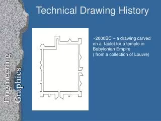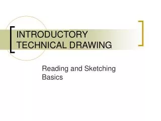
Perspective Drawing for Technical Illustration
480 likes | 1.01k Vues
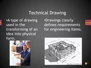
Learn one-point, two-point, and three-point perspective techniques for creating accurate technical drawings. Understand the use of picture plane, horizon, vanishing points, and ground lines. Develop skills in creating orthographic drawings and incorporating details. Use drawing grids to enhance precision in your illustrations.

Perspective Drawing for Technical Illustration
E N D
Presentation Transcript
Perspective Drawing for Technical Illustration References: 1, 2, 3
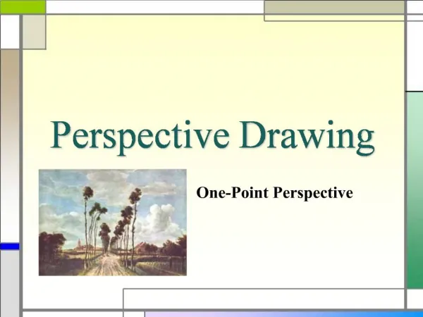
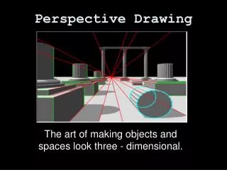
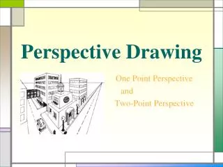
One-Point Perspective High Eye level Low Eye level Central Eye level
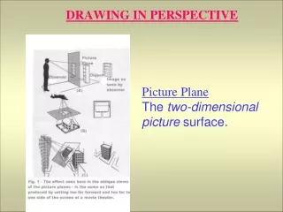
1. Set Picture Plane, Station Point, Horizon, VP, and Ground Line One-Point Perspective Picture Plane Horizon VP Ground Line Station Point
2. Place plan and front views [image] Plane Horizon VP Ground Line 3. Sketch front face Station Point [camera]
4. From front face, draw lines to VP Picture Plane Horizon VP Ground Line Station Point
5. Project back to picture plane Picture Plane Horizon VP Ground Line 6. Draw side face Station Point
Picture Plane Horizon VP Ground Line Station Point 6. Draw top face
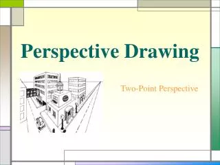
Two-Point Perspective Place the Plan View Set Station Point (SP)
(Eye Line) The location of horizon and ground lines are infinitely variable. The location of the Horizon Line will depend on whether you want to view the object from above eye level or below eye level. The location of the Ground Line in relation to the Horizon Line will determine how far above or below eye level the object will be viewed.
From SP, draw two // lines, intersecting at Picture plane Create LVP & RVP Place Side Elevation on Ground Line Project height to vertical line
Draw lines to LVP & RVP Project width to Picture Plane; Draw vertical lines
Set depth of floor
Set depth of wall
Termesphere (ref) 1-,2-,3-point perspective
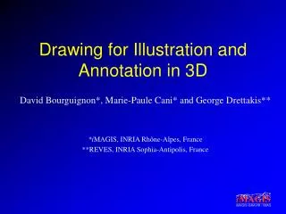
Floor plan Architecture: from a 3D model to a perspective image Plan view + 3D dimensions Perspective view
Floor plan focal length viewing plane observer Architecture: from a 3D model to a perspective image 2nd vanishing point 1st vanishing point
Architecture: from a 3D model to a perspective image Perspective view 1st v.p. 2nd v.p. Horizon line Floor in perspective Observer’s height Ground line
Reference height Architecture: from a 3D model to a perspective image Perspective view Horizon line Observer’s height Ground line
Reference height Architecture: from a 3D model to a perspective image Perspective view Horizon line Observer’s height Ground line
Reference height Architecture: from a 3D model to a perspective image Perspective view Horizon line Door height Ground line