Download
1 / 39
390 likes | 422 Vues
Explore the cutting-edge Coherent X-ray Imaging Instrument (CXI) developed by Sébastien Boutet, providing unparalleled imaging capabilities for biomolecules and nanoparticles. Learn about CXI's goals, instrument overview, X-ray optics, sample environments, detectors, and operating modes.

E N D
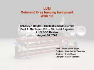
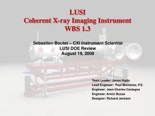
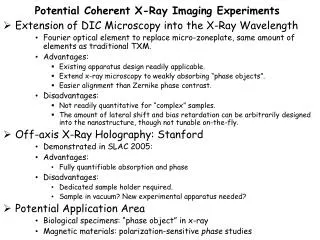
Coherent X-ray Imaging Instrument WBS 1.3 Sébastien Boutet CXI Instrument Scientist April 21, 2009
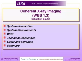
Outline • CXI Science • CXI Goals and Physics Requirements • CXI Instrument Overview • X-ray Optics and Diagnostics • KB Mirror Systems • Sample Environments • Detector • Operating Modes • Work Breakdown Structure • Early Science Instrument Scope • Instrument Team • Summary
Coherent Diffractive Imaging of Biomolecules One pulse, one measurement Particle injection LCLS pulse Wavefront sensor or second detector Noisy diffraction pattern Combine many measurements into 3D dataset Combined Data Set Reconstruction Data Frames
Coherent X-ray Imaging Science Protein molecule injection LCLS detector detector To mass spectrometer X-ray diffraction pattern • 3D bio imaging beyond the damage limit • Single injected reproducible biomolecules that can’t be crystallized • Proteins • Membrane Proteins • Viruses • Molecular complexes • Molecular machines • Biomolecular structure determination from nanocrystals • No need for large high quality crystals • 2D bio imaging beyond the damage limit • Live hydrated cells with particle injector • Nanoparticles • Quantum dots • Amorphous nanoparticles • High fluence X-ray-matter interactions • Damage studies during the pulse • Effect of tamper layers on damage
CXI Instrument Goals/Requirements • Goals • Perform imaging of single particles at highest spatial resolution achievable using single LCLS pulses • Image biological nanoparticles beyond the classical damage limit using single LCLS pulses • Global Requirements (SP-391-000-19) • Tailor and characterize X-ray beam parameters • Spatial Profile • Intensity • Repetition rate • Deliver the sample to the beam and control its environment • Key Performance Parameters • 4-20 keV energy range • Using the fundamental and third harmonic • 0.1-0.01% energy resolution • Particle Injector • 10-1000 nm size range
CXI Instrument Location Near Experimental Hall AMO X-ray Transport Tunnel SXR XPP CXI Endstation XCS Source to Sample distance : ~ 440 m Far Experimental Hall
Far Experimental Hall CXI Control Room Lab Area XCS Control Room Hutch #6 X-ray Correlation Spectroscopy Instrument Coherent X-ray Imaging Instrument
CXI Instrument Overview Guard Slits Diagnostics Photon Shutter XRT Attenuators Pulse Picker Reference Laser Guard Slits Diagnostics Guard Slits 1 µm KB Mirrors Diagnostics Guard Slits 0.1 µm KB Mirrors 0.1 µm Sample Environment Particle Injector Ion TOF-MS Detector Stage FEH Hutch 5 Guard Slits Diagnostics 1 µm Sample Environment Particle Injector Ion TOF-MS Detector Stage Wavefront Monitor Beam Dump
CXI Instrument Overview Particle injector LCLS Beam Sample Chamber Precision Instrument Stand Detector Stage
X-ray Optics and Diagnostics Guard Slits Diagnostics Photon Shutter XRT Attenuators Pulse Picker Reference Laser Guard Slits Diagnostics Guard Slits 1 µm KB Mirrors Diagnostics Guard Slits 0.1 µm KB Mirrors 0.1 µm Sample Environment Particle Injector Ion TOF-MS Detector Stage FEH Hutch 5 Guard Slits Diagnostics 1 µm Sample Environment Particle Injector Ion TOF-MS Detector Stage Wavefront Monitor Beam Dump
X-ray Optics and Diagnostics Guard Slits Diagnostics Photon Shutter XRT Attenuators Pulse Picker Reference Laser Guard Slits Diagnostics Guard Slits 1 µm KB Mirrors Diagnostics Guard Slits 0.1 µm KB Mirrors 0.1 µm Sample Environment Particle Injector Ion TOF-MS • LUSI Attenuator\Pulse Picker System • Excellent Optical Quality • > 3 steps per decade of attenuation above 6 keV • > 1012 attenuation < 17 keV • Isolate 3rd harmonic from fundamental • Tailor rep rate up to 10 Hz Detector Stage FEH Hutch 5 Guard Slits Diagnostics 1 µm Sample Environment Particle Injector Ion TOF-MS Detector Stage Wavefront Monitor Beam Dump
Reference Laser Guard Slits Diagnostics Photon Shutter XRT Attenuators Pulse Picker Reference Laser Guard Slits Diagnostics Guard Slits 1 µm KB Mirrors Diagnostics Guard Slits • Purpose • Rough alignment of the experiment without the X-ray beam • Requirements • On/Off states • Beam size • Smallest possible at the end of the hutch • Stability • 5% of FWHM (short term) • 15% of FWHM (long term) • Useable with any part of the instrument vented to air • Window valves • Aligned to the unfocused FEL beam to within 100 microns 0.1 µm KB Mirrors 0.1 µm Sample Environment Particle Injector Ion TOF-MS Detector Stage FEH Hutch 5 Guard Slits Diagnostics 1 µm Sample Environment Particle Injector Ion TOF-MS Detector Stage Wavefront Monitor Beam Dump
CXI 1 µm KB Mirrors Guard Slits Diagnostics Photon Shutter XRT Attenuators Pulse Picker Reference Laser Guard Slits Diagnostics Guard Slits 1 µm KB Mirrors Diagnostics Guard Slits • Purpose • Produce a 1 µm focus • Focal lengths • 8.2 m for M1 • 7.8 m for M2 • Requirements • 350 mm clear aperture • 3.4 mrad maximum incidence angle • SiC coating • <1 nm rms height error over entire mirror • 2-11 keV energy range • Space for 2 coating strips 0.1 µm KB Mirrors 0.1 µm Sample Environment Particle Injector Ion TOF-MS Detector Stage FEH Hutch 5 Guard Slits Diagnostics 1 µm Sample Environment Particle Injector Ion TOF-MS Detector Stage Wavefront Monitor Beam Dump
CXI 1 µm Sample Environment Guard Slits Diagnostics Photon Shutter XRT Attenuators Pulse Picker Reference Laser Guard Slits Diagnostics Guard Slits 1 µm KB Mirrors Diagnostics Guard Slits • Purpose • Position samples on grids and apertures • Maintain high vacuum • Requirements • Accommodate multiple experiments configurations • Fixed targets • Injected particles • Interface with • Detector Stage downstream and upstream • Ports for • Particle Injector • Ion TOF • Lasers • Vacuum better than 10-7 torr • Rapid access • Large volume for flexibility • Compatible only with 1 micron KB System 0.1 µm KB Mirrors 0.1 µm Sample Environment Particle Injector Ion TOF-MS Detector Stage FEH Hutch 5 Guard Slits Diagnostics 1 µm Sample Environment Particle Injector Ion TOF-MS Detector Stage Wavefront Monitor Beam Dump
CXI 0.1 µm KB Mirrors/Sample Environment Guard Slits Diagnostics Photon Shutter XRT Attenuators Pulse Picker Reference Laser Guard Slits Diagnostics Guard Slits 1 µm KB Mirrors Diagnostics Guard Slits • Purpose • Produce a ~100 nm focus • Focal lengths • 0.9 m for M1 • 0.5 m for M2 • Requirements • Identical to 1 micron KB System in every way except for the mirror curvature • Integrated system with 0.1 micron Sample Chamber due to close proximity • Extend vacuum enclosure by ~600 mm for sample area • Separate both parts of the vacuum enclosure with valve and window 0.1 µm KB Mirrors 0.1 µm Sample Environment Particle Injector Ion TOF-MS Detector Stage FEH Hutch 5 Guard Slits Diagnostics 1 µm Sample Environment Particle Injector Ion TOF-MS Detector Stage Wavefront Monitor Beam Dump
CXI Particle Injector Guard Slits Diagnostics Photon Shutter XRT Attenuators Pulse Picker Reference Laser Guard Slits Diagnostics Guard Slits 1 µm KB Mirrors Diagnostics Guard Slits • Purpose • Deliver support-free single particles to the LCLS beam • Requirements • < 250 microns Particle beam focus • > 50 % Transmission • 10 mm XZ Translation • 10 – 1000 nm Particle size range • Aerodynamic lens • Stack of concentric orifices with decreasing openings. • Particle beam diagnostics • Charge detectors • Particle beam viewer 0.1 µm KB Mirrors 0.1 µm Sample Environment Particle Injector Ion TOF-MS Detector Stage FEH Hutch 5 Guard Slits Diagnostics 1 µm Sample Environment Particle Injector Ion TOF-MS Detector Stage Wavefront Monitor Beam Dump
CXI Ion TOF Guard Slits Diagnostics Photon Shutter XRT Attenuators Pulse Picker Reference Laser Guard Slits Diagnostics Guard Slits 1 µm KB Mirrors Diagnostics Guard Slits • Purpose • Detect ions produced by exploding sample • Provide a veto trigger signal when a particle was hit by the beam • Identify unwanted particles • Requirements • 1 Atomic Mass Unit resolution • Up to 100 AMU detection • 1 GHz digitization • Does not interfere with imaging detector • Design based on AMO Ion Spectrometer 0.1 µm KB Mirrors 0.1 µm Sample Environment Particle Injector Ion TOF-MS Detector Stage FEH Hutch 5 Guard Slits Diagnostics 1 µm Sample Environment Particle Injector Ion TOF-MS Detector Stage Wavefront Monitor Beam Dump
CXI Detector Guard Slits Collaboration with the Gruner Group at Cornell University Diagnostics Photon Shutter XRT Attenuators Pulse Picker Reference Laser Guard Slits Diagnostics Guard Slits 1 µm KB Mirrors Diagnostics Guard Slits • 2D Pixel Array Detector • High resistivity Silicon (500 µm) for direct x-ray conversion. • Reverse biased for full depletion. • Bump-bonding connection to CMOS ASIC. • <1 photon readout noise • 110x110 µm2 pixels • 1520x1520 pixels • 103 dynamic range • 120 Hz readout • Tiled detector, permits variable ‘hole’ size • Detector not in CXI LUSI scope • Part of LCLS Project scope 0.1 µm KB Mirrors 0.1 µm Sample Environment Particle Injector Ion TOF-MS Detector Stage FEH Hutch 5 Guard Slits Diagnostics 1 µm Sample Environment Particle Injector Ion TOF-MS Detector Stage Wavefront Monitor Beam Dump
CXI Detector Stage Guard Slits Diagnostics Photon Shutter XRT Attenuators Pulse Picker Reference Laser Guard Slits Diagnostics Guard Slits 1 µm KB Mirrors Diagnostics Guard Slits • Purpose • Center the detector hole on the direct beam • Position the detector at the appropriate distance from the interaction region • Requirements • Range along the beam : 50-2400 mm • Non-continuous • Vacuum better than 10-7 torr • Diagnostics behind the detector for alignment • Valve to isolate the detector vacuum • Short term stability • 1 micron • 10 µrad (pitch/yaw) 0.1 µm KB Mirrors 0.1 µm Sample Environment Particle Injector Ion TOF-MS Detector Stage FEH Hutch 5 Guard Slits Diagnostics 1 µm Sample Environment Particle Injector Ion TOF-MS Detector Stage Wavefront Monitor Beam Dump
Operating Modes • Photon operating modes described in LCLS Document 1.6.009 • CXI operation requires SH1, SH2 and S5 open • CXI has three modes: • “1 micron” Mode • Use 1 micron KB mirrors and 1 micron Sample Environment • “0.1 micron” Mode • Use 0.1 micron KB mirrors and 0.1 micron Sample Environment • “Unfocused” Mode • No focusing optic and 1 micron Sample Environment
CXI with 1 micron and Unfocused Beam Optics & Diagnostics Optics & Diagnostics Diagnostics & Wavefront Monitor 1 micron Sample Environment 1 micron KB Reference Laser
CXI with 0.1 micron Beam Optics, Diagnostics and Wavefront Monitor Optics & Diagnostics 0.1 micron KB & Sample Environment Reference Laser
Science Team • Specifications and instrument concept developed with the science team. The CXI team leaders • Janos Hajdu, Uppsala University (leader) • Henry Chapman, DESY, University of Hamburg • John Miao, UCLA
The design is based on FEL experiments - Highlights from Nature journals Over 50 publications in total
Science Team Involvement • Roles of the Team Leaders are defined in a Letter of Understanding • Define the original scope of the instrument • Approved the LUSI scope by signing the Physics Requirements Document • Approved the overall design choices of the CXI team • Approved a list of scope additions should contingency become available • Receive a weekly report on the CXI progress • Attended a formal annual Team Leaders meeting
General User Community Involvement • A workshop was held on October 17 2008 • Applications of Coherent X-rays at the LCLS • http://www-conf.slac.stanford.edu/coherence2008/default.asp • A CXI Proposal Preparation Workshop will be held during the LCLS User’s Meeting in Fall 2009 • Similar workshops were held for AMO and XPP • http://www-conf.slac.stanford.edu/amo/2008/ • http://www-conf.slac.stanford.edu/xpp/2008/ • Extremely enthusiastic response from prospective users • The European XFEL held a workshop to define the scope of the CXI equivalent instrument on November 20-22 2008 • http://xray.bmc.uu.se/spb/ • The CXI team was involved • Presented the CXI plans • The workshop confirmed the CXI plans • Some preliminary XFEL plans were changed based on input from the CXI team • The user community demands for the XFEL instrument are what CXI was already planning • Two of the three CXI Team Leaders were present at the workshop
General User Community Involvement • A workshop was held on October 17 2009 Applications of Coherent X-rays at the LCLS http://www-conf.slac.stanford.edu/coherence2008/default.asp CXI Team leaders
Summary Instrument accommodates a wide variety of cutting edge research capabilities and fulfills the CD-0 mission The CXI instrument is versatile: X-ray optics can tailor FEL parameters for users Sample environment can accommodate multiple experimental configurations User operation start planned for 2011 First call for proposals Spring 2010 CXI 2nd Scientist Position Opened CXI Website: http://lcls.slac.stanford.edu/cxi/
Assembly with Positioning Plate Removed • Modular design • Allows for addition of tiles in the future • Initial detector • 8 modules • Variable hole size Cross-roller rails support positioning plate and provides low-friction, repeatable motion Torque ring rotates to translate Quadrant Rafts and change aperture size Martin Nordby & Matthew Swift