Download
1 / 35
350 likes | 464 Vues
Explore the transformative journey of optical fiber technology from high attenuation rates to low dispersion characteristics, enabling efficient communications over long distances.

E N D
Optical Communications: Circuits, Systems and Devices Chapter 3: Optical DevicesOptical Fibers Sharif University of Technology
Chapter 3 Optical Devices Optical Fibers Brief History of Optical Fiber Technology (1 of 2)• Mid-1960s: Attenuation in bulk glass was ∼ 500dB/km - Attempted guiding structures including surface-wave devices - Attenuation reduction:◦ In 1971 Kapron et al. at Corning made a fiber with α ≈ 20dB/km◦ By 1977, experimental fibers had α < 0.5 dB/km at λ = 1.2 μm Sharif University of Technology
Chapter 3 Optical Devices Optical Fibers Brief History of Optical Fiber Technology (2 of 2)• Dispersion produces pulse broadening and limits bit rate - Unclad fiber was widely used for imaging and short-distance transmission◦ Very rapid pulse broadening → not suitable for communications - Core-cladding fibers were named “weakly guiding fibers” in 1971 ◦ Essential for achieving low dispersion Sharif University of Technology
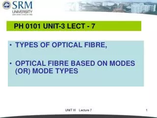
Chapter 3 Optical Devices Optical Fibers Optical Fiber Types for Communications (1 of 3)• Unclad fiber - Not used for communications because of very rapid pulse spreading due to high intermodal dispersion• Multimode clad fiber (used in LANs and for short-haul applications) - Core refractive index > cladding refractive index - Usually the core refractive-index profile is graded to reduce pulse spreading due to intermodal dispersion - The most widely installed type has a core diameter of 62.5 μm and a cladding diameter of 125 μm Sharif University of Technology
Chapter 3 Optical Devices Optical Fibers Optical Fiber Types for Communications (2 of 3)• Single-mode clad fiber (used for long-haul applications) - Step-index: Core refractive index is a constant - Profiled index: Core refractive index is designed to achieve favorable group-velocity-dispersion characteristics - Core diameter ∼ 10 μm Sharif University of Technology
Chapter 3 Optical Devices Optical Fibers Optical Fiber Types for Communications (3 of 3) Sharif University of Technology
Chapter 3 Optical Devices Optical Fibers Optical Fiber Waveguide Modes (1 of 2)• Analysis involves Bessel functions and a lot of vector calculus - In a step-index fiber there are only two media, the core (refractive index n1) and the cladding (refractive index n2) - The mode that has a cutoff frequency equal to 0 is a hybrid electricmode (HE11), in which both Ez and Hz are non-zero◦ There are two polarizations with the same frequency and propagation constant (degenerate HE11 modes with different polarizations)◦ For 0 < V < 2.405 the HE11 mode is the only mode that can propagate (all others are below the cutoff frequency)◦ This is called “single-mode” operation, despite the fact that there are two degenerate modes Sharif University of Technology
Optical Fiber Waveguide Modes (2 of 2)• Assume a is the core radius, thenthe normalized frequency and normalized propagation constant are Chapter 3 Optical Devices Optical Fibers Sharif University of Technology 8
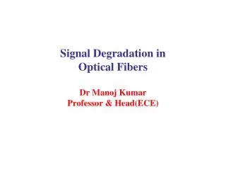
Chapter 3 Optical Devices Optical Fibers Properties of Fibers for Communications (1 of 2)• Numerical aperture - Useful only for multimode fibers and incoherent sources (e.g. LEDs)• Attenuation - Imperfect light coupling into the fiber - Absorption - Scattering• Dispersion - Modal Dispersion: different modes propagate at different group velocities; Meaningful only for multimode fibers - Chromatic (waveguide+material) Dispersion - Polarization mode dispersion Sharif University of Technology
Chapter 3 Optical Devices Optical Fibers Properties of Fibers for Communications (2 of 2)• Birefringence (Or Double refraction) - Polarization-maintaining fiber - Polarization-mode dispersion in non-polarization-maintaining fiber• Fiber Non-linearities - Stimulated Raman Scattering (SRS) - Stimulated Brillouin Scattering (SBS) - Self phase modulation (SPM) - Cross phase modulation (XPM) - Four wave mixing Sharif University of Technology
Chapter 3 Optical Devices Optical Fibers Numerical Aperture (1 of 2)• It is defined aswhere θmis the system’s maximum acceptance half-angle and n is the refractive index of the outside material Sharif University of Technology
Chapter 3 Optical Devices Optical Fibers Numerical Aperture (2 of 2)• If n = 1, then 0 ≤ NA ≤ 1 - 0 means that no light gets into the system - 1 means that all of the light propagating towards the system gets in - Power into system ∝(NA)2• Typically, NA= 0.15 for single mode fiber and 0.3 for MMF Sharif University of Technology
Chapter 3 Optical Devices Optical Fibers Dispersion • Dispersion is the property that the velocity of light depends on the optical frequency or the mode of propagation in a waveguide• Dispersion causes the duration and shape of an optical pulse to change in the course of propagation, causing bit errors in reception• Causes of dispersion: - Material dispersion: Frequency dependence of the refractive index - Waveguide dispersion: Frequency dependence of the propagation constant in a fiber mode - Intermodal dispersion: Different fiber modes have different propagation constants at the same frequency, making pulses launched simultaneously in different modes arrive at the receiver at different times - Polarization mode dispersion: birefringence, different refractive index in x and y direction leading to PMD Sharif University of Technology
Chapter 3 Optical Devices Optical Fibers Intermodal dispersionin multimode fibers (1 of 5)• Different modes of propagation in a waveguide correspond to different E and H field patterns - For a fiber with a sufficiently small core radius, there is only one propagating mode• Different modes propagate at different speeds because some modes take a longer path through a fiber than others• Also called multipath dispersion• The differential mode delay for step-index fiber is the difference in arrival times of two pulses launched into different modes - vc ≈ c/ncore is the propagation velocity of a monochromatic wave in the core of the fiber (Units: μs, ns or ps) Sharif University of Technology
Chapter 3 Optical Devices Optical Fibers Intermodal dispersionin multimode fibers (2 of 5)• Differential mode delay is important for LAN technologies• where θc = critical angle and • For a fiber of length L, the difference in arrival times of a pulse that travels along an axial ray and one that travels along a meridional ray at the critical angle is where Sharif University of Technology
Chapter 3 Optical Devices Optical Fibers Intermodal dispersionin multimode fibers (3 of 5)• Numerical value for clad, weakly guiding fiber (ncore ≈ nclad ≈ 1.5 andΔ ≈ 3 × 10⁻³)• Requirement for minimal inter symbol interference: where B = bit rate• Maximum length bit-rate product for weakly guiding step-index fiber:• Numerical values for weakly guiding fiber, for which ncore ≈ nclad ≈ 1.5: - Step-index multimode (Δ ≈ 3×10⁻³): BL < 67 Mb-km/s (MHz-km) Sharif University of Technology
Chapter 3 Optical Devices Optical Fibers Intermodal dispersionin multimode fibers (4 of 5)• Unclad multimode (Δ ≈ 0.33): BL < 0.4 Mb-km/s (MHz-km) - Because 90◦ − θc,unclad >> 90◦ − θc,clad the path difference per km of fiber between an axial ray and a ray that bounces back and forth at the critical angle is much greater for unclad fiber than for clad, weakly guiding fiber• Graded-index multimode fiber can have higher values of BL than step-index multimode fiber - The α-profile used to model graded-index fiber is where a = core radius and Sharif University of Technology
Chapter 3 Optical Devices Optical Fibers Intermodal dispersionin multimode fibers (5 of 5) - The value α = 2 produces zero intermodal dispersion in the paraxial approximation of geometrical optics◦ The actual bit-rate limit that can be achieved with α = 2 is Sharif University of Technology
Chromatic dispersion - chromatic (Group-velocity) dispersion: A single pulse in a single fiber mode contains a range of frequencies, each of which propagates at a different velocity Chapter 3 Optical Devices Optical Fibers September, 2008 Sharif University of Technology 19
Chapter 3 Optical Devices Optical Fibers Group Velocity Dispersion• Group-velocity dispersion in a single fiber mode - The phase velocity of a wave, vp = ω/β, is the velocity at which a monochromatic wave travels - The group velocity, vg = dω/dβ, is the velocity of a pulse◦ A pulse is a superposition of many frequencies, by Fourier analysis◦ If ω is not a linear function of β, then vg≠ vp - The differential group delay, d(L/vg), is the difference in arrival times of two pulses centered at different wavelengths◦ Chromatic dispersion: (units: ps per nm-km) Sharif University of Technology
Chapter 3 Optical Devices Optical Fibers Group Velocity Dispersion in Single Mode Fiber • Difference in arrival times of waves at wavelengths λ and λ+Δλ: - Material dispersion: - Waveguide dispersion: Sharif University of Technology
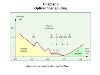
Attenuation (1 of 3)• Basic formula: - α is the attenuation coefficient(units are cm−1 or c) - Loss in dB = 10(log10 e)αL ≈ 4.343 αL - Practical units of the attenuation coefficient are dB/km or dB/m• Origins of attenuation in silica fibers in the 1.2 - 1.6 μm region - Absorption◦ UV-tail absorption (absorption with Geo2 in UV)◦ IR-tail absorption (absorption with molecular structure in IR)◦ External absorption (mainly with OH−1 ) Chapter 3 Optical Devices Optical Fibers September, 2008 Sharif University of Technology 22
Attenuation (2 of 3) - Scattering ◦ Rayleigh: caused by small variations in the refractive index of glass as it cools ◦ Attenuation coefficient: αR = Cλ−4 where C ≈ 0.7−0.9 (dB/km)(μm)4◦ Important for λ < 1.2μm Chapter 3 Optical Devices Optical Fibers Sharif University of Technology 23
Attenuation (3 of 3)• Attenuation of light in silica fiber: Chapter 3 Optical Devices Optical Fibers OH−1 Rayleigh scattering UV-tail IR-tail September, 2008 Sharif University of Technology 24
Bending Loss Chapter 3 Optical Devices Optical Fibers September, 2008 Sharif University of Technology 25
Overview of Optical Fiber Manufacturing• An optical fiber is drawn from a preform - Dimensions are ∼ 1 meter in length by 2 cm in diameter - Refractive-index profile is the same (relative to the outside diameter) as in the finished fiber◦ The core is doped with GeO2 or P2O5 to increase the refractive index◦ B2O3 and F can be used in the cladding to decrease the refractive index Chapter 3 Optical Devices Optical Fibers Sharif University of Technology 26
Methods for fabricating a preform Chapter 3 Optical Devices Optical Fibers Sharif University of Technology 27
Drawing an Optical Fiber Chapter 3 Optical Devices Optical Fibers Sharif University of Technology 28
Coating and Cabling• Coating - Deposited immediately after the fiber is pulled - Purpose: Protection from scratch• Cable - Jacket contains one to many fiber bundles, each inside a tube - Purposes:◦ Mechanical strength◦ Protection from H2O and other environmental chemicals◦ Prevention of micro bending losses Chapter 3 Optical Devices Optical Fibers Sharif University of Technology 29
Chapter 3 Optical Devices Optical Fibers Nonlinear Optics• Comprises some of the most striking effects in physics - Light of a single color enters a transparent substance - Different colors emerge on the other side• Examples: - Second harmonic generation: ω in, 2ω out - Stimulated Raman scattering - Stimulated Brillouin scattering Sharif University of Technology
Chapter 3 Optical Devices Optical Fibers Nonlinear Optical Effects in Fibers (1 of 3)• When an optical electric field is stronger than about 10−5 to 10−6 of a typical electric field inside an atom (∼ 1011 V/m), there are small but measurable departures of the linear relation between electric field and induced dipole moment per unit volume, even in “ordinary” materials such as silica glass• Single-mode fibers in long-haul telecommunication systems have all the right conditions for producing nonlinear optical effects - High power/unit area in the core → high optical electric field - Long propagation distance at high power/unit area Sharif University of Technology
Chapter 3 Optical Devices Optical Fibers Nonlinear Optical Effects in Fibers (2 of 3)• Important nonlinear effects for optical communications include: - Changes in the refractive index which are proportional to optical power◦ Self-phase modulation broadens the signal spectrum - Four-wave mixing - Optical amplifier based on raman scattering Sharif University of Technology
Nonlinear Optical Effects in Fibers (3 of 3)• Stimulated Brillouin scattering: - An optical signal is in reality a very strong electromagnetic field. This field causes mechanical vibrations in the fibre which produce a regularly varying pattern of very slight differences in the refractive index. The Brillouin Scattering effect is caused by light being reflected by the diffraction grating created by the regular pattern of RI changes Chapter 3 Optical Devices Optical Fibers September, 2008 Sharif University of Technology 33
Nonlinear Optical Effects in Fibers (3 of 3)• Stimulated Raman scattering: - caused by a similar mechanism to the one which produces SBS - the interactions involved are due to molecular vibrations rather than acoustic ones. - In WDM systems at very high powers - power has been transferred from the shorter wavelength to the longer one (from the higher energy wave to the lower energy one). -This power transfer is caused by interactions of the light with vibrating molecules. Chapter 3 Optical Devices Optical Fibers September, 2008 Sharif University of Technology 34
Chapter 3 Optical Devices Optical Fibers Questions ? Sharif University of Technology