Download
1 / 49
540 likes | 1.3k Vues
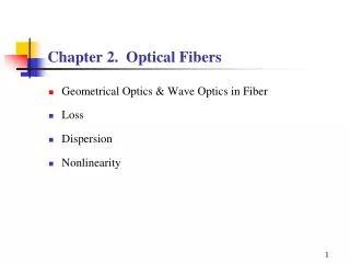
Chapter 2 Optical Fibers: Structures, Waveguiding & Fabrication. Theories of Optics.

E N D
Chapter 2Optical Fibers: Structures, Waveguiding & Fabrication
Theories of Optics • Light is an electromagentic phenomenon described by the same theoretical principles that govern all forms of electromagnetic radiation. Maxwell’s equations are in the hurt of electromagnetic theory & is fully successful in providing treatment of light propagation. Electromagnetic optics provides the most complete treatment of light phenomena in the context of classical optics. • Turning to phenomena involving the interaction of light & matter, such as emission & absorption of light, quantum theory provides the successful explanation for light-matter interaction. These phenomena are described by quantum electrodynamics which is the marriage of electromagnetic theory with quantum theory. For optical phenomena, this theory also referred to as quantum optics. This theory provides an explanation of virtually all optical phenomena.
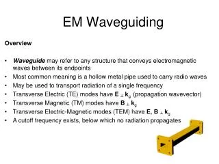
Quantum Optics Electromagnetic Optics Wave Optics Ray Optics • In the context of classical optics, electromagentic radiation propagates in the form of two mutually coupled vector waves, an electric field-wave & magnetic field wave. It is possible to describe many optical phenomena such as diffraction, by scalar wave theory in which light is described by a single scalar wavefunction. This approximate theory is called scalar wave optics or simply wave optics. When light propagates through & around objects whose dimensions are much greater than the optical wavelength, the wave nature of light is not readily discerned, so that its behavior can be adequately described by rays obeying a set of geometrical rules. This theory is called ray optics. Ray optics is the limit of wave optics when the wavelength is very short.
Engineering Model • In engineering discipline, we should choose the appropriate & easiest physical theory that can handle our problems. Therefore, specially in this course we will use different optical theories to describe & analyze our problems. In this chapter we deal with optical transmission through fibers, and other optical waveguiding structures. Depending on the structure, we may use ray optics or electromagnetic optics, so we begin our discussion with a brief introduction to electromagnetic optics, ray optics & their fundamental connection, then having equipped with basic theories, we analyze the propagation of light in the optical fiber structures.
Electromagnetic Optics • Electromagnetic radiation propagates in the form of two mutually coupled vector waves, an electric field wave & a magnetic field wave. Both are vector functions of position & time. • In a source-free, linear, homogeneous, isotropic & non-dispersive media, such as free space, these electric & magnetic fields satisfy the following partial differential equations, known as Maxwell’ equations: [2-1] [2-2] [2-3] [2-4]
In Maxwell’s equations, E is the electric field expressed in [V/m], H is the magnetic field expressed in [A/m]. • The solution of Maxwell’s equations in free space, through the wave equation, can be easily obtained for monochromatic electromagnetic wave. All electric & magnetic fields are harmonic functions of time of the same frequency. Electric & magnetic fields are perpendicular to each other & both perpendicular to the direction of propagation, k, known as transverse wave (TEM). E, H & k form a set of orthogonal vectors.
E x k Direction of Propagation x z z y B y An electromagnetic wave is a travelling wave which has time varying electric and magnetic fields which are perpendicular to each other and the direction of propagation, z. Electromagnetic Plane wave in Free space S.O.Kasap, optoelectronics and Photonics Principles and Practices, prentice hall, 2001
Linearly Polarized Electromagnetic Plane wave [2-5] [2-6] Angular frequency [rad/m] [2-7] Wavenumber or wave propagation constant [1/m] Wavelength [m] intrinsic (wave) impedance [2-8] velocity of wave propagation [2-9]
E and B have constant phase in this xy plane; a wavefront z E E k Propagation B E x E = E sin( w t–kz ) x o z A plane EM wave travelling along z , has the same E (or B ) at any point in a x y given xy plane. All electric field vectors in a given xy plane are therefore in phase. The xy planes are of infinite extent in the x and y directions. S.O.Kasap, optoelectronics and Photonics Principles and Practices, prentice hall, 2001
Wavelength & free space • Wavelength is the distance over which the phase changes by . • In vacuum (free space): [2-10] [2-11]
EM wave inMedia • Refractive index of a medium is defined as: • For non-magnetic media : [2-12] Relative magnetic permeability Relative electric permittivity [2-13]
Intensity & power flow of TEM wave • The poynting vector for TEM wave is parallel to the wavevector k so that the power flows along in a direction normal to the wavefront or parallel to k. The magnitude of the poynting vector is the intensity of TEM wave as follows: [2-14]
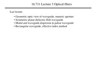
Connection between EM wave optics & Ray optics According to wave or physical optics viewpoint, the EM waves radiated by a small optical source can be represented by a train of spherical wavefronts with the source at the center. A wavefront is defined a s the locus of all points in the wave train which exhibit the same phase. Far from source wavefronts tend to be in a plane form. Next page you will see different possible phase fronts for EM waves. When the wavelength of light is much smaller than the object, the wavefronts appear as straight lines to this object. In this case the light wave can be indicated by a light ray, which is drawn perpendicular to the phase front and parallel to the Poynting vector, which indicates the flow of energy. Thus, large scale optical effects such as reflection & refraction can be analyzed by simple geometrical process called ray tracing. This view of optics is referred to as ray optics or geometrical optics.
Wave fronts (constant phase surfaces) Wave fronts Wave fronts k P l l E r k l P O z A perfect plane wave A perfect spherical wave A divergent beam (a) (b) (c) Examples of possible EM waves rays S.O.Kasap, optoelectronics and Photonics Principles and Practices, prentice hall, 2001
General form of linearly polarized plane waves Any two orthogonal plane waves Can be combined into a linearly Polarized wave. Conversely, any arbitrary linearly polarized wave can be resolved into two independent Orthogonal plane waves that are in phase. [2-15] Optical Fiber communications, 3rd ed.,G.Keiser,McGrawHill, 2000
Elliptically Polarized plane waves [2-16] Optical Fiber communications, 3rd ed.,G.Keiser,McGrawHill, 2000
Circularly polarized waves [2-17] Optical Fiber communications, 3rd ed.,G.Keiser,McGrawHill, 2000
Laws of Reflection & Refraction Reflection law: angle of incidence=angle of reflection Snell’s law of refraction: [2-18] Optical Fiber communications, 3rd ed.,G.Keiser,McGrawHill, 2000
Transmitted (refracted) light k t n Evanescent wave 2 n > n 1 2 k k i r TIR Incident Reflected light light ( c ) ( a ) ( b ) Light wave travelling in a more dense medium strikes a less dense medium. Depending on the incidence angle with respect to , which is determined by the ratio of the refractive indices, the wave may be transmitted (refracted) or reflected. (a) (b) (c) and total internal reflection (TIR). Total internal reflection, Critical angle Critical angle [2-19]
Phase shift due to TIR • The totally reflected wave experiences a phase shift however which is given by: • Where (p,N) refer to the electric field components parallel or normal to the plane of incidence respectively. [2-20]
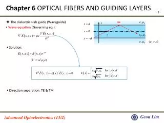
Optical waveguiding by TIR:Dielectric Slab Waveguide Propagation mechanism in an ideal step-index optical waveguide. Optical Fiber communications, 3rd ed.,G.Keiser,McGrawHill, 2000
Launching optical rays to slab waveguide [2-21] Maximum entrance angle, is found from the Snell’s relation written at the fiber end face. [2-22] Numerical aperture: [2-23] [2-24]
Optical rays transmission through dielectric slab waveguide O For TE-case, when electric waves are normal to the plane of incidence must be satisfied with following relationship: [2-25] Optical Fiber communications, 3rd ed.,G.Keiser,McGrawHill, 2000
Note • Home work 2-1) Find an expression for ,considering that the electric field component ofoptical wave is parallel to the plane of incidence (TM-case). • As you have seen, the polarization of light wave down the slab waveguide changes the condition of light transmission. Hence we should also consider the EM wave analysis of EM wave propagation through the dielectric slab waveguide. In the next slides, we will introduce the fundamental concepts of such a treatment, without going into mathematical detail. Basically we will show the result of solution to the Maxwell’s equations in different regions of slab waveguide & applying the boundary conditions for electric & magnetic fields at the surface of each slab. We will try to show the connection between EM wave and ray optics analyses.
EM analysis of Slab waveguide • For each particular angle, in which light ray can be faithfully transmitted along slab waveguide, we can obtain one possible propagating wave solution from a Maxwell’s equations or mode. • The modes with electric field perpendicular to the plane of incidence (page) are called TE (Transverse Electric) and numbered as: Electric field distribution of these modes for 2D slab waveguide can be expressed as: wave transmission along slab waveguides, fibers & other type of optical waveguides can be fully described by time & z dependency of the mode: [2-26]
y z TE modes in slab waveguide Optical Fiber communications, 3rd ed.,G.Keiser,McGrawHill, 2000
Modes in slab waveguide • The order of the mode is equal to the # of field zeros across the guide. The order of the mode is also related to the angle in which the ray congruence corresponding to this mode makes with the plane of the waveguide (or axis of the fiber). The steeper the angle, the higher the order of the mode. • For higher order modes the fields are distributed more toward the edges of the guide and penetrate further into the cladding region. • Radiation modes in fibers are not trapped in the core & guided by the fiber but they are still solutions of the Maxwell’ eqs. with the same boundary conditions. These infinite continuum of the modes results from the optical power that is outside the fiber acceptance angle being refracted out of the core. • In addition to bound & refracted (radiation) modes, there are leaky modes in optical fiber. They are partially confined to the core & attenuated by continuously radiating this power out of the core as they traverse along the fiber (results from Tunneling effect which is quantum mechanical phenomenon.) A mode remains guided as long as
Optical Fibers: Modal Theory (Guided or Propagating modes) & Ray Optics Theory Optical Fiber communications, 3rd ed.,G.Keiser,McGrawHill, 2000 Step Index Fiber
Modal Theory of Step Index fiber • General expression of EM-wave in the circular fiber can be written as: • Each of the characteristic solutions is called mth mode of the optical fiber. • It is often sufficient to give the E-field of the mode. [2-27]
The modal field distribution, , and the mode propagation constant, are obtained from solving the Maxwell’s equations subject to the boundary conditions given by the cross sectional dimensions and the dielectric constants of the fiber. • Most important characteristics of the EM transmission along the fiber are determined by the mode propagation constant, , which depends on the mode & in general varies with frequency or wavelength. This quantity is always between the plane propagation constant (wave number) of the core & the cladding media . [2-28]
At each frequency or wavelength, there exists only a finite number of guided or propagating modes that can carry light energy over a long distance along the fiber. Each of these modes can propagate in the fiber only if the frequency is above the cut-off frequency, , (or the source wavelength is smaller than the cut-off wavelength) obtained from cut-off condition that is: • To minimize the signal distortion, the fiber is often operated in a single mode regime. In this regime only the lowest order mode (fundamental mode) can propagate in the fiber and all higher order modes are under cut-off condition (non-propagating). • Multi-mode fibers are also extensively used for many applications. In these fibers many modes carry the optical signal collectively & simultaneously. [2-29]
Fundamental Mode Field Distribution Mode field diameter Polarizations of fundamental mode Optical Fiber communications, 3rd ed.,G.Keiser,McGrawHill, 2000
Ray Optics Theory (Step-Index Fiber) Skew rays Each particular guided mode in a fiber can be represented by a group of rays which Make the same angle with the axis of the fiber. Optical Fiber communications, 3rd ed.,G.Keiser,McGrawHill, 2000
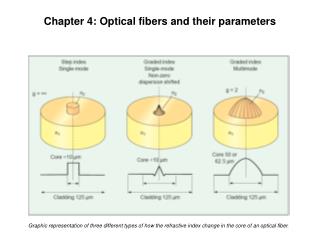
Different Structures of Optical Fiber Optical Fiber communications, 3rd ed.,G.Keiser,McGrawHill, 2000
Mode designation in circular cylindrical waveguide (Optical Fiber) The electric field vector lies in transverse plane. The magnetic field vector lies in transverse plane. TE component is larger than TM component. TM component is larger than TE component. y l= # of variation cycles or zeros in direction. m= # of variation cycles or zeros in r direction. r x z Linearly Polarized (LP) modes in weakly-guided fibers ( ) Fundamental Mode:
Two degenerate fundamental modes in Fibers (Horizontal & Vertical Modes) Optical Fiber communications, 3rd ed.,G.Keiser,McGrawHill, 2000
Mode propagation constant as a function of frequency • Mode propagation constant, , is the most important transmission characteristic of an optical fiber, because the field distribution can be easily written in the form of eq. [2-27]. • In order to find a mode propagation constant and cut-off frequencies of various modes of the optical fiber, first we have to calculate the normalized frequency, V, defined by: [2-30] a: radius of the core, is the optical free space wavelength, are the refractive indices of the core & cladding.
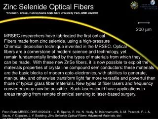
Plots of the propagation constant as a function of normalized frequency for a few of the lowest-order modes
Single mode Operation • The cut-off wavelength or frequency for each mode is obtained from: • Single mode operation is possible (Single mode fiber) when: [2-31] [2-32]
Single-Mode Fibers • Example: A fiber with a radius of 4 micrometer and has a normalized frequency of V=2.38 at a wavelength 1 micrometer. The fiber is single-mode for all wavelengths greater and equal to 1 micrometer. MFD (Mode Field Diameter): The electric field of the first fundamental mode can be written as: [2-33]
Birefringence in single-mode fibers • Because of asymmetries the refractive indices for the two degenerate modes (vertical & horizontal polarizations) are different. This difference is referred to as birefringence, : [2-34] Optical Fiber communications, 3rd ed.,G.Keiser,McGrawHill, 2000
Fiber Beat Length • In general, a linearly polarized mode is a combination of both of the degenerate modes. As the modal wave travels along the fiber, the difference in the refractive indices would change the phase difference between these two components & thereby the state of the polarization of the mode. However after certain length referred to as fiber beat length, the modal wave will produce its original state of polarization. This length is simply given by: [2-35]
Multi-Mode Operation • Total number of modes, M, supported by a multi-mode fiber is approximately (When V is large) given by: • Power distribution in the core & the cladding: Another quantity of interest is the ratio of the mode power in the cladding, to the total optical power in the fiber, P, which at the wavelengths (or frequencies) far from the cut-off is given by: [2-36] [2-37]