Download
1 / 78
910 likes | 1.42k Vues
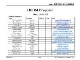
OFDM Signaling. By Assad Saleem. OFDM Signaling. WiMAX and numerous emerging wireless systems employ OFDM signaling High bandwidth utilization and efficiency Less vulnerable to channel distortions and multipath Supports high data rate communications and flexible bandwidth on demand

E N D
OFDM Signaling By Assad Saleem
OFDM Signaling • WiMAX and numerous emerging wireless systems employ OFDM signaling • High bandwidth utilization and efficiency • Less vulnerable to channel distortions and multipath • Supports high data rate communications and flexible bandwidth on demand • Can be realized using fast, low cost, and readily available DSP hardware
OFDM Applications • OFDM is widely used in the communication industry. - Global standard for asymmetric digital subscriber line (ADSL), - European standard for digital audio broadcasting (DAB), - Wireless local area networks (LANs), - WiFi (IEEE 802.11), and - WiMAX (IEEE 802.16)
Frequency Division Multiplexing (FDM) Spectrum • Basic Multiple User Signal Structure [1] Harris, F., Orthogonal Frequency Division Multiplexing OFDM, Vehicular Technology Conference, 2004.
OFDM Spectrum [1] Harris, F., Orthogonal Frequency Division Multiplexing OFDM, Vehicular Technology Conference, 2004.
Spectrum of (a) an individual carrier and (b) an OFDM signal [16] National Instruments, Orthogonal Frequency Division Multiplexing available at www.ni.com, 2004.
Orthogonal Carriers • Two functions f(x) and g(x) are orthogonal over a the period [a, b] if and only if they satisfy the following equation
Orthogonal Carriers • Since OFDM uses sinusoidal basis functions. Let’s assume two sinusoidal functions and then, where, T = 1/f.
Spectrum of an OFDM (orthogonal frequency division multiplexing) communication system [16] National Instruments, Orthogonal Frequency Division Multiplexing available at www.ni.com, 2004.
OFDM Signal Generation • The input bit stream is mapped in a serial to parallel fashion into complex I,Q pair coefficients based on an m-ary QAM constellation (m(k)). • N complex coefficients weight N sinusoidal basis functions which are transformed to generate an OFDM symbol where, T is the active symbol period, N is the number of carriers, and m[k] is the kth symbol in the message symbol sequence for k in [0, N-1]
OFDM Signal Modulation • OFDM symbol s(t) can be denoted in discrete time as where, continuous time t is replaced by discrete time n, and continuous time active symbol period T is replaced by N • One can recognize the Inverse Discrete Fourier Transform (IDFT) in the above expression • Hence, an OFDM symbol can be generated from a sequence of IQ symbols by taking their Inverse Discrete Fourier Transform (IDFT)
OFDM Signal Generation [1] Harris, F., Orthogonal Frequency Division Multiplexing OFDM, Vehicular Technology Conference, 2004.
OFDM Signal Demodulation • Since all the carriers are orthogonal to each other and noting the previous representation of an OFDM symbol • A symbol which was used to modulate a particular carrier say the ith harmonic of the fundamental frequency, can be recovered or demodulated just by integrating that carrier frequency. • Although the spectra of carriers overlap but still the modulated symbols can be extracted from the carriers, as is shown by above mathematical equation.
OFDM Signal Demodulation • Also, if we replace integral by summation, “t” by “n,” and “T” by “N” in previous expression, we get the following expression where, is the estimate of the symbol modulating the carrier whose frequency is the product of the fundamental frequency and “i.” • As it is obvious that the above expression is the Discrete Fourier Transform (DFT) • Therefore, an OFDM signals can be demodulated by DFT
OFDM Signal Demodulation [1] Harris, F., Orthogonal Frequency Division Multiplexing OFDM, Vehicular Technology Conference, 2004.
Basic OFDM Transceiver System [1] Harris, F., Orthogonal Frequency Division Multiplexing OFDM, Vehicular Technology Conference, 2004.
Basic Structure of an OFDM System with Channel Impairments [4] WiMAX Forum, Mobile WiMAX – Part 1 : A Technical Overview and Performance Evaluation, 2006.
Adjacent symbol interference (ASI) symbol smearing due to channel [1] Harris, F., Orthogonal Frequency Division Multiplexing OFDM, Vehicular Technology Conference, 2004.
Insertion of Guard Interval between adjacent symbols to suppress ASI [1] Harris, F., Orthogonal Frequency Division Multiplexing OFDM, Vehicular Technology Conference, 2004.
Cyclic Prefix Insertion [16] National Instruments, Orthogonal Frequency Division Multiplexing available at www.ni.com, 2004.
OFDM symbol time structure showing insertion of Cyclic Prefix [4] WiMAX Forum, Mobile WiMAX – Part 1 : A Technical Overview and Performance Evaluation, 2006.
Cyclic Prefix inserted in the Guard Interval to suppress Adjacent Channel Interference (ACI) [1] Harris, F., Orthogonal Frequency Division Multiplexing OFDM, Vehicular Technology Conference, 2004.
Basic OFDM Transmitter [16] National Instruments, Orthogonal Frequency Division Multiplexing available at www.ni.com, 2004.
OFDM Symbol Structure and Sub-channelization • Synchronization Delay Compensation [4] WiMAX Forum, Mobile WiMAX – Part 1 : A Technical Overview and Performance Evaluation, 2006.
OFDM Signal Generation • Guard Bins [1] Harris, F., Orthogonal Frequency Division Multiplexing OFDM, Vehicular Technology Conference, 2004.
OFDM Channel Characteristics for IEEE 802.16 [12] IEEE Computer Society, and IEEE Microwave Theory and Techniques Society, 802.16 IEEE Standard for Local and Metropolitan Area Networks Part 16 : Air Interface for Fixed Broadband Wireless Access Systems, 2004.
OFDM Symbol Parameters for IEEE 802.16 [12] IEEE Computer Society, and IEEE Microwave Theory and Techniques Society, 802.16 IEEE Standard for Local and Metropolitan Area Networks Part 16 : Air Interface for Fixed Broadband Wireless Access Systems, 2004.
OFDM Pilot Tones for IEEE 802.16 [12] IEEE Computer Society, and IEEE Microwave Theory and Techniques Society, 802.16 IEEE Standard for Local and Metropolitan Area Networks Part 16 : Air Interface for Fixed Broadband Wireless Access Systems, 2004.
Channel Delay function [d3,timeoff] =DelayInterp(d1,timeoff); % Received data time delay (offset) % % Routine call: d2 =Delay(d1) % % Input parameter: d1 % Output parameter: d3 global interpfactor; global Bins_fft; if nargin<2 timeoff=interpfactor*32+floor(interpfactor*Bins_fft/2*rand(1)); end d2 = d1(timeoff:timeoff+interpfactor*Bins_fft-1); d3 = d2(1:interpfactor:end); return
Channel Noise function [d1chan_n] =Channel(d1_twice,i); % Channel Distortion % % Routine call: d1chan_n =Channel(d1_twice) % % Input parameter: d1_twice (no channel) % Output parameter: d1chan_n (data distorted by channel) global Bins_fft;global Doffset;global Data_setsize;global chan; global SNRdB;global Mpsk;global Mqam;global p_num;global p_vect; k=i; normnoise=randn(2*k*Bins_fft,1); normnoise=sqrt(2*(Data_setsize/2+2)/(Bins_fft/4))*normnoise/sqrt(sum(normnoise.^2)); normnoise=normnoise/(10^(SNRdB/20)); chan=[1 .2 0 0.02 0 j*0.1]; chan=chan/sum(chan); d1chan=conv([zeros(2*Bins_fft,1); d1_twice]',chan); %d1chan_n=d1chan+0.0435*(randn(1,4*Bins_fft+5)+j*randn(1,4*Bins_fft+5)); d1chan_n=d1_twice+normnoise; return
Phase Correction due to Channel Delay phaseptone=ptone_fd2./ptone_fd1; refphased=360*(timeoff-1)/(Bins_fft); ptonepdiff=angle(phaseptone)*180/pi; pdptonepdiff=diff(ptonepdiff); pdptonepdiff2=pdptonepdiff + 360*(pdptonepdiff<0); phaseshift=(pdptonepdiff2./pbinsteps); for mmm=2:(length(p_ind)-1) padd=round(((phaseshift(mmm-1)-phaseshift(mmm))*pbinsteps(mmm))/360); pdptonepdiff2(mmm)=pdptonepdiff2(mmm)+360*padd; phaseshift(mmm)=pdptonepdiff2(mmm)/pbinsteps(mmm); end phasesteps=mean(phaseshift); CorrectPVect=exp(-sqrt(-1)*(p_ind+Doffset)*(phasesteps*pi/180)); phase2=mean(angle((ptone_fd2.*CorrectPVect)./ptone_fd1)); CorrectPVect=CorrectPVect*exp(-sqrt(-1)*phase2); angle((ptone_fd2.*CorrectPVect)./ptone_fd1); CorrectVect(1:Bins_fft/2,1)=exp(-sqrt(-1)*(0:Bins_fft/2-1)'*(phasesteps*pi/180)); CorrectVect=CorrectVect*exp(-sqrt(-1)*phase2); CorrectVect(Bins_fft:-1:(Bins_fft/2+2),1)=conj(CorrectVect(2:Bins_fft/2)); % Apply the phase correction vector fd_correct =fd2 .* CorrectVect;
Software Defined Radio • Advancement in Integrated Circuits Technology: - higher densities, - higher speeds, - RF integrated circuits, and - mixed signal integrated circuits • Allows implementation of advanced digital signal processing concepts