OFDM
OFDM. Adaptive Modulation Reduction of Peak-to-Average Power Ratio Channel estimation OFDM in frequency selective fading channel . Puja Thakral Silvija Kokalj-Filipovic Youngsik Lim Sadhana Gupta. OUTLINE. Introduction to OFDM Adaptive Modulation

OFDM
E N D
Presentation Transcript
OFDM Adaptive Modulation Reduction of Peak-to-Average Power Ratio Channel estimation OFDM in frequency selective fading channel Puja Thakral Silvija Kokalj-Filipovic Youngsik Lim Sadhana Gupta
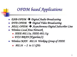
OUTLINE • Introduction to OFDM • Adaptive Modulation • Reduction of Peak-to-Power Average Ratio • OFDM in Frequency Selective Fading Channel • Channel Estimation • Conclusions
Adaptive Modulation In OFDM ,adaptive bit loading algorithms set the modulation level in each frequency band such that a predefined total number of bits are transmitted with minimum power.Adaptive Modulation independently optimizes the modulation scheme to each sub carrier so that spectral efficiency is maximized,while maintaining a target Bit Error Rate(BER).
OFDM Block StructureWith Adaptive Modulation S/P MODULATOR 1 IFFT FFT DEMODULATOR 1 P/S MODULATOR 2 DEMODULATOR 2 FREQUENCY SELECTIVE CHANNEL + MODULATOR N DEMODULATOR N CHANNEL ESTIMATION ADAPTIVE BIT AND POWER ALLOCATION
Various Algorithms in Adaptive Modulation • For a given target BER and bit-rate, the total transmit power can be minimized by optimally distributing the power and bit-rate across the sub channels. • For a given target BER and power transmitted,the total bit-rate can be maximized. • For a given target power and bit rate,the total BER can be minimized.
ALGORITHM • Compute the subchannel signal to noise ratios. • Compute the number of bits for the ith subchannel based on the formula, b`(i)=log2(1+SNR(i)) • Round the value of b`(i) down to b(i). • Restrict b(i) to take the values 0,1,2,4,6,8 • Compute the energy for the ith subchannel based on the number of bits initially assigned to it using the formula e(b(i))=(2^b(i)-1)/SNR
FUTURE WORK • Feasibility study of MIMO OFDM systems • Simulation of MIMO OFDM system with adaptive modulation and multilevel transmit power control.
Peak To Average Power Ratioin OFDM Causes, Effects and Reduction Methods Silvija Kokalj-Filipovic
Summary • Goal: reducing maximum output power to near average power by limiting the set of transmitted signals through coding • Complementary Golay Sequences have peak-to-average power less then 2 • Reed-Muller Coding used to produce these sequences out of information sequence
Stochastic Structure • In accordance with CLT, when large number of modulated carriers (N) are combined into a composite time-domain signal by means of IFFT (they are assumed to be independent, since the assigned data symbols are iid (µ0, σ0 )), it leads to near Gaussian pdf of amplitude, where the amplitude value exceeds certain threshold value A with probability Q(A-µ/σ), and • µ ~ Nµ0 σ ~ Nσ0
Since we have N independent points in the composite time signal: • For BPSK modulation we’ll have ~ Gaussian distribution of the amplitude • For MPSK and M-QAM modulations (which both have 2-dimensional space: I and Q component ) we have a Rayleigh distribution (square root of the sum of squares of I & Q Gaussian random variables). • Cumulative distribution of power: F (z) = 1-e-z
Definition of PAPR (PMEPR) • PAPR & PAR: Peak-To-Average Power Ratio • PMEPR: Peak-To-Mean Envelope Power Ratio • Crest factor of x(t): square root of PAR • Definition: PAR = (||x||∞)2 / E[(||x||2) 2]
Crest Factor - notation The crest factor of u(t): square root of PMEPR where is the maximum absolute value of u(t) and is the rms of u(t):
Effects of PAPR • The power amplifiers at the transmitter need to have a large linear range of operation. • nonlinear distortions and peak amplitude limiting introduced by the High Power amplifier (HPA) will produce inter-modulation between the different carriers and introduce additional interference into the system. • additional interference leads to an increase in the Bit Error Rate (BER) of the system. • one way to avoid non-linear distortion is by forcing the amplifier to work in its linear region. Unfortunately such solution is not power efficient and thus not suitable for wireless communication. • The Analog to Digital converters and Digital to Analog converters need to have a wide dynamic range and this increases complexity. • if clipped, it leads to in-band distortion (additional noise) and ACI (out-of-band radiation)
Classification of PAR reduction methods • BLOCK CODING (Golay sequences) • CLIP EFFECT TRANSFORMATION • PROBABILISTIC TECHNIQUES: • Selective Mapping (SLM) and Partial Transmit Sequences (PTS) • Tone Reduction (TR) and Tone Injection (TI)
Representation of OFDM signal • In the bandpass with = the multi-carrier (multitone) signal can be represented as • where corresponds to initial phase of the tones, i.e. the effect of modulating data.
Representation of OFDM signal assumingt is the frequency and 1/T is the sampling period of sequence is the discrete complex sequence of information data (phase-mapped). Crest factor depends on the maximum absolute value of the multicarrier signal, and that one depends on the “amplitude spectrum” of the complex sequence Observation: OFDM has somewhat inverted logic – we are looking for flat PSD in time domain, while autocorrelation is taken in frequency domain Choosing to be complementary Golay sequence crest factor of less than 6dB (PAPR of 3 dB) can be obtained
Proof: • Aperiodic correlation Cx(z) of some sequence The Fourier transform Sx(f) of sequence • Definition: Two sequences and of the length N form a complementary pair if • Golay complementary sequences have that property. where Ts is the sampling period of sequence
N carrier OFDM; H-PSK modulation • Information-bearing sequence is in fact an OFDM codeword and is the primitive H-root of unity (j in QPSK case) • Instantaneous Envelope Power For complementary sequences:
Theory behind Reed-Muller codes • An rth order Reed-Muller code R(r,m) is the set of all binary strings (vectors) of length n= 2m associated with the Boolean polynomials p(x1, x2, …, xm) of degree at most r. • A Boolean polynomial is a linear combination of Boolean monomials with coefficients in F2. A Boolean monomial p in the variables x1, x2, …, xm is the expression of the form: • P = x1r1 x2r2 …, xmrm where ri {0,1,2..} and 1 ≤ i ≤ m. • Degree of a monomial is deduced from it reduced form (after rules xixj = xjxi and xi2 = xi are applied), and it is equal to the number of variables. This rule extends to polynomials • Ex. of a polynomial of degree 3: • q = x1+ x2+x1 x2+ x1 x2 x3 • How to associate Boolean monomial in m variables to a vector with 2m entries: • a vector associated with monomial of degree 0 (1) is a string of length 2m where each entry is 1. • a vector associated with monomial x1 is 2m-1 ones followed by 2m-1 zeros. • a vector associated with monomial x2 is 2m-2 ones followed by 2m-2 zeros, then another 2m-2 ones followed by 2m-2 zeros. • a vector associated with monomial xi is a pattern of 2m-i ones followed by 2m-i zeros, repeated until 2m values are defined.
Example of RM generator matrix • m = 5: RM(1,5) has six rows • X0: 1 1 1 1 1 1 1 1 1 1 1 1 1 1 1 1 1 1 1 1 1 1 1 1 1 1 1 1 1 1 1 1 • X1: 0 0 0 0 0 0 0 0 0 0 0 0 0 0 0 0 1 1 1 1 1 1 1 1 1 1 1 1 1 1 1 1 • X2: 0 0 0 0 0 0 0 0 1 1 1 1 1 1 1 1 0 0 0 0 0 0 0 0 1 1 1 1 1 1 1 1 • X3: 0 0 0 0 1 1 1 1 0 0 0 0 1 1 1 1 0 0 0 0 1 1 1 1 0 0 0 0 1 1 1 1 • X4: 0 0 1 1 0 0 1 1 0 0 1 1 0 0 1 1 0 0 1 1 0 0 1 1 0 0 1 1 0 0 1 1 • X5: 0 1 0 1 0 1 0 1 0 1 0 1 0 1 0 1 0 1 0 1 0 1 0 1 0 1 0 1 0 1 0 1
Relationship between Reed-Muller codes and Complementary Golay Sequences • In the binary case, Golay pairs and sets occur in the first-order Reed-Muller code RM(1,m) within the second-order Reed-Muller code (cosets). • Each coset has assigned coset representative of the form: • where is any permutation of the sequence of generator matrix rows – see graph with rows as hypercube vertices : number of elements in the Galois field
Conclusions and Further Work • Result: complete elimination of clipping noise • Drawback: serious overhead (low bandwidth utilization – 17/32) • Further work: • implementation of Tone Reservation Algorithm and Comparison with Golay Sequences • Extension of the method to Golay sequences that do not form complementary pairs but have satisfying PAR (coset representatives of different forms)
Conclusions and Further Work • Result: complete elimination of clipping noise • Drawback: serious overhead (low bandwidth utilization – 17/32) • Further work: • implementation of Tone Reservation Algorithm and Comparison with Golay Sequences • Extension of the method to Golay sequences that do not form complementary pairs but have satisfying PAR (coset representatives of different forms)
Problem Description • Signal distortion in frequency selective fading channel • What is the cyclic prefix ? • How is the interference eliminated with cyclic prefix? • How is its performance without the cyclic prefix.
Transmission over frequency selective fading channel(*) (t) Pulse Shaping Tx Receive Filter Rx Channel ch + t=nTs (n) (n) H0+H1z-1 h(n) + + (*) Z. Wang, G.B. Giannakis, Wireless Multicarrier Communications. IEEE 2000 Signal Processing Magazine
Channel Model (**) • Channel response Dispersive in time, Static over block interval Selective in frequency Black : Average , Gray : a realization of the channel (**) Frequency selective Flat fading channel(Naftali Chayat in IEEE P802.11-97/96)
N+L Memory from the past block N U H What is H0 and H1?
Tcp H0+H1z-1 Rcp + How is IBI deleted ?
Cyclic prefix effect on OFDM OFDM Input bits S/P Mapping IFFT FFT Demapping P/S Output bits . . . . . . . . . . . . . . . + No IBI plus simpler equalizer
Simulation configuration • Perfect channel estimation , QPSK, Fixed sub-channel power • Zero Forcing equalization • 64 sub-carriers • Simulation Results
802.11a Pilot subcarrier placement Subcarrier - 21 - 7 0 7 21 numbers - 31 to 32 Pilot subcarrier placement used L = 7 14 22 14 7 Subcarr ier 0 7 21 43 57 64 numbers 1 to 64
Conclusions and future work: Low pass filtering interpolation shows best performance among evaluated interpolation methods as reported in literature, especially for larger values of Trms. Future work: Evaluation of performance of differential modulation Evaluation with Doppler frequency shift Primary Reference: Channel Estimation Techniques based on Pilot Arrangement in OFDM Systems Coleri, et al, IEEE Transactions on Broadcasting, p223 - 229 September 2002