Download
1 / 23
230 likes | 252 Vues
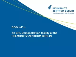
Explore advanced electron beam technology at the Helmholtz-Zentrum in Berlin with a focus on high current and short pulses for storage ring applications.

E N D
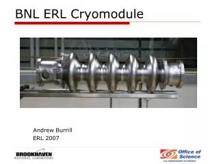
BERLinPro An ERL Demonstration facility at the HELMHOLTZ ZENTRUM BERLIN
BERLinPro: ERL demonstration facility to prepare the ground for a few GeV ERL @ Berlin-Adlershof Goal: Main components: • 100MeV, 100mA beam • Small emittance, rel. short bunches • High current: to address needs of storage ring users • Show energy recovery • Explore limits of ERL (multiturn, injection energy) • Show different operational modes: high current (100mA, 2ps), short pulses (10mA, 100fs), ??, => superiority of the ERL concept to storage rings • SC-RF gun • Booster module – Cornell development with minor modifications • Merger: C-chicane, 4 rectangular dipoles • Linac: based on Tesla technology, modified for high current • Return arc: TBA • Second loop option
Finances and time table : • ‚go ahead‘ for gun development • R&D money for gun development secured • Further approval process for entire budget 2010 beam from 1.6 cell gun cavity in HoBiCaT Conceptual design 2011 Technical layout (TDR) 5 years after approval: first recirculated electrons
SRF Gun 5-10 MeV Main Linac SRF Module Merger Section 100 MeV 1.5 MeV SRF Booster Spent Beam Return Arc Beam Dump Undulator tests Beam Manipulation GUN DEVELOPMENT
BERLinPro gun: Staged approach A high brightness source which can deliver high average current and short pulses. Stage 1-Beam Dynamics: Produce beam with cold gun in existing HoBiCaT cryomodule. Nb cavity with Pb-coated cathode (J. Sekutowicz & Co), UV laser (MBI), sc solenoid and beam diagnostics. Stage 2-Cathode integration: Extend HoBiCaT bunker, new cryomodule, cathode preparation infrastructure. Produce 1 to 10 mA with CsK2Sb cathode, green laser (MBI). In parallel, test gun cavities and new RF coupler (>100kW) in HoBiCaT. Stage 3-High currentoperation: Build SRF gun for BERLinPro (high rep. rate) From J. Sekutowicz, Proc. of PAC09 Courtesy of Thorsten Kamps
Stage 1 setup in HoBiCaT 1.6 cell cavity, sc-solenoid, Helium supply Stage 1 diagnostic beam line View screens, stripline, current monitor, emittance measurement, energy measurement
SRF Gun 5-10 MeV Main Linac SRF Module Merger Section 100 MeV 1.5 MeV SRF Booster Spent Beam Return Arc Beam Dump Undulator tests Beam Manipulation MERGER DESIGN CONSIDERATIONS
Space charge forces: compatible with emittance compensation scheme Zigzag chicane: (Brookhaven) • equal focussing in both planes • 2. order dispersion not 0 • Small trajectory displacement • Fixed relation D1/D2 • „Geometrically challenging“ • (vertical construction in Brookhaven) C-chicane: Higher order dispersion: intrinsically cancelled by C-chicane with rectangular magnets • Easier to incorporate in machine • Flexible drift lengths • Offset adjustable by drift length • Vertical focussing
ASTRA: Emittance for Zigzag / C- chicane for increasing bunch charge and different energy spread (correlated) C-chicane Gaussian bunch: e x,y = 1.0 p mrad s x,y = 1.0 mm s z = 1.0 mm b x,y = 20.0 m a x,y = 0 Zigzag
Bunch lengthening in merger due to energy spread / space charge Effect is reduced when going to 10 MeV injection energy.
Emittance depends strongly on bunch length: Charge sz Compression 77pC 6ps 3 or more 10pC 1ps 10 or more Emittance vrs. bunch length 77pC 10pC • Gaussian bunch: • E = 10 MeV • e x,y = 1.0 p mrad • s x,y = 1.0 mm • b x,y = 20.0 m • x,y = 0 s E = 20keV
By Lars-Johan Lindgren, MAX-lab Lambertson magnet: Good idea?? • Last merger dipole deflects high energy beam by up to 4° • => extra chicane necessary • Lambertson: High energy beam travels in • field free region, injected low energy beam runs parallel • Lambertson would reduce 4° to less than 0.14°, which is rather an orbit correction
Last merger dipole Lambertson? Steerer a d L1 a [°] as a function of d, L1 0.025rad = 1.432deg. • High energy beam deflected by 1/10: 0.14° mean 2.5cm offset after 10m linac • Steering for HE beam is necessary • Place for HE optical elements before Lambertson
SRF Gun 5-10 MeV Main Linac SRF Module Merger Section 100 MeV 1.5 MeV SRF Booster Spent Beam Return Arc Beam Dump Undulator tests Beam Manipulation Linac:
100 MeV Linac: • 1.3 GHz • Start with multicell TESLA and adapt this for CW and high current • Single cryomodule with 6-7 cavities • 7 cells/cavity (?) • Application „Verbundforschungsantrag“: federal funding for a collaboration with Univ. Rostock and Dortmund for the calculation of HOM • Options for HOMs: Ferrite loads, waveguide dampers • HoBiCaT test
SRF Gun 5-10 MeV Main Linac SRF Module Merger Section 100 MeV 1.5 MeV SRF Booster Spent Beam Return Arc Beam Dump Undulator tests Beam Manipulation RECIRCULATOR - ARC
E E = E0 cos (wt +f0) Df = p • head with higher E • gives compression with “normal” arc R56 t X chirp at deceleration doubles inacceptable energy spread Df = p – 2 f0 Path length management: • Short bunches require pathlength adjustment • Second loop option: • 100MeV: 1. turn: L=(n+1/2) lrf • 200MeV: 1. turn: L= n lrf (lrf/2=12cm) • Variable injection energy alters path length in merger & splitter for HE beam • 20o bend @ 5-20MeV = 1-4o @ 100MeV => 0.5cm DL =2 f0/2p*lrf =2-3cm f0 =20deg. Courtesy of Michael Abo-Bakr
SB D D0 yK f1 r1 X1 f0 X0 r0 3 Approaches to pathlength adjustment: • 1 - Brookhaven: Build arc on sledge, mechanical adjustment • very precise • expensive • slow • 2 - C-chicane • long @ 100MeV: 2-3m • CSR – bunches are short • 3 - Incorporate into the arc Angle and offset for 6cm additional pathlength Courtesy of Michael Abo-Bakr
Radiation safety requirements: • Different ‚league‘ than storage rings • Drive costs • =>drive beamloss requirements • Permissable beamloss:<1e-5? => Too little space for shielding above ground => Consider construction underground reduced shielding, vibrations and temperature fluctuations at comparable costs
BESSY II Cryogenic plant
All dimensions preliminary Building: Storage Ring Hall 55m 6.4m 6.0m 15m