CHAPTER 6 SHEET METAL WORKING PROCESSES
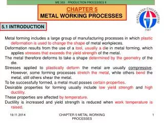
ME 333 PRODUCTION PROCESSES II. CHAPTER 6 SHEET METAL WORKING PROCESSES. 6 . 1 INTRODUCTION. Sheet metalworking includes cutting and forming operations performed on relatively thin sheets of metal (0.4-6 mm).

CHAPTER 6 SHEET METAL WORKING PROCESSES
E N D
Presentation Transcript
ME 333 PRODUCTION PROCESSES II CHAPTER 6 SHEET METAL WORKING PROCESSES 6.1INTRODUCTION Sheet metalworking includes cutting and forming operations performed on relatively thin sheets of metal (0.4-6 mm). The tooling used to perform sheet metalwork is called punch and die. Most sheet metal operations are performed on machine tools called presses. The term stamping press is used to distinguish these presses from forging and extrusion presses. The sheet metal products are called stampings. The commercial importance of sheet metalworking is significant. The number of consumer and industrial products that include sheet metal parts: automobile and truck bodies, airplanes, railway cars and locomotives, farm and construction equipment, small and large appliances, office furniture, computers and office equipment, and more. Sheet metal parts are generally characterized by high strength, good dimensional tolerances, good surface finish, and relatively low cost. CHAPTER 6 SHEET METAL WORKING PROCESSES
ME 333 PRODUCTION PROCESSES II Sheet-metal processing is usually performed at room temperatures (cold working). The exemptions are when the stock is thick, the metal is brittle, or the deformation is significant. These are usually cases of warm working rather than hot working. CHAPTER 6 SHEET METAL WORKING PROCESSES
ME 333 PRODUCTION PROCESSES II • The three major categories of sheet-metal processes: • cutting (shearing, blanking, piercing) • bending • drawing. • Cutting is used to separate large sheets into smaller pieces, to cut out a part perimeter, or to make holes in a part. • Bending and drawing are used to form sheet metal parts into their required shapes. Fig.6.1 Some cutting operations CHAPTER 6 SHEET METAL WORKING PROCESSES
ME 333 PRODUCTION PROCESSES II Classification of Sheet Metalworking Processes Fig.6.2 Basic sheet metalworking operations: (a) bending, (b) drawing, and (c)shearing; (1) as punch first contacts sheet and (2) after cutting. Forceand relative motion are indicated by F and v CHAPTER 6 SHEET METAL WORKING PROCESSES
ME 333 PRODUCTION PROCESSES II Classification of Sheet Metalworking Processes Fig.6.2 Basic processes involved in forming sheet metal components. (a) Processes involving local deformation. CHAPTER 6 SHEET METAL WORKING PROCESSES
ME 333 PRODUCTION PROCESSES II 6.2. PIERCING AND BLANKING A commonly used piercing-blanking die set and related terms are shown in the following figure. Fig.6.3 Components of a punch and die CHAPTER 6 SHEET METAL WORKING PROCESSES
ME 333 PRODUCTION PROCESSES II Blanking and punching Blanking and punching are similar sheet metal cutting operations that involve cutting the sheet metalalong a closed outline. If the part that is cut out is the desired product, the operation is called blankingand the product is called blank. If the remaining stock is the desired part, the operation is calledpunching. Both operations are illustrated on the example of producing a washer: Starting stock produced byshearing operation from abig metal sheet Fig.6.4 Steps in production of washer CHAPTER 6 SHEET METAL WORKING PROCESSES
ME 333 PRODUCTION PROCESSES II The cutting of metal between die components is a shearing process in which the metal is stressed in shear between two cutting edges to the point of fracture, or beyond its ultimate strength. The metal is subjected to both tensile and compressive stresses; stretching beyond the elastic limit occurs; then plastic deformation, reduction in area, and, finally, fracturing starts and becomes complete. Blanking punch diameter= Db-2c Blanking die diameter= Db Hole punch diameter= Dh Hole die diameter= Dh+2c Fig.6.5 Shearing of sheet metal between punch and die CHAPTER 6 SHEET METAL WORKING PROCESSES
ME 333 PRODUCTION PROCESSES II The cutting of metal between die components is a shearing process in which the metal is stressed in shear between two cutting edges to the point of fracture, or beyond its ultimate strength. The metal is subjected to both tensile and compressive stresses; stretching beyond the elastic limit occurs; then plastic deformation, reduction in area, and, finally, fracturing starts and becomes complete. Fig.6.5 Shearing of sheet metal between punch and die CHAPTER 6 SHEET METAL WORKING PROCESSES
ME 333 PRODUCTION PROCESSES II Engineering analysis of metal cutting: Cutting of sheet metal is accomplished by a shearing action between two sharp edges. The shearingaction is illustrated in the figure: • Fig. 6.6. Shearing of sheet metal between two cutting edges: • just before the punch contacts work; • punch begins to push into work, causing plastic deformation; • punch compresses and penetrates into work, causing a smooth cut surface; and • fracture is initiated at the opposing cutting edges that separate the sheet. • Symbols v and F indicate motion and applied force, respectively. Fig.6.3 Shearing CHAPTER 6 SHEET METAL WORKING PROCESSES
ME 333 PRODUCTION PROCESSES II At the top of the cut surface is a region called the rollover. This corresponds to the depression made by the punch in the work prior to cutting. It is where initial plastic deformation occured in the work. Just below the rollover is a relatively small region called the burnish. This results from penetration of the punch into the work before fracture began. Beneath the burnish is the fractured zone, a relatively rough surface of the cut edge where continued downward movement of the punch caused fracture of the metal. Finally, at the bottom of the edge is a burr, a sharp corner on the edge caused by elongation of the metal during final seperation of the two pieces. CHAPTER 6 SHEET METAL WORKING PROCESSES
ME 333 PRODUCTION PROCESSES II 6.2.1. Engineering Analysis_CLEARANCE Process parameters in sheet metal cutting are clearence between punch and die, stock thickness, type of metal and its strength and length of the cut Clearancec in a shearing operation is the space between the mating members of a die set (e.g.punch and die). For optimum finish of cut edge, proper clearance is necessary and is a function of the kind, thickness, and hardness of the work material. In an ideal cutting operation the punch penetrates the material to a depth equal to about 1/3 of its thickness before fracture occurs, and forces an equal portion of the material into the die opening. Common die clearances (linear clearance) are 2-5% of the material thickness. Angular clearance is gradient given to the hole in the die such that cut material will easily be removed. Angular clearance is usually ground from 0.25⁰ to 1.5⁰ per side. CHAPTER 6 SHEET METAL WORKING PROCESSES
ME 333 PRODUCTION PROCESSES II The correct clearance depends on sheet-metaltype and thickness t: c = a*t where a is the allowance (a = 0.075 for steels and 0.060 for aluminum alloys). If the clearance is not set correctly, either an excessive force or an oversized burr can occur: Fig.6.7 Effect of clearance: (Left) clearance toosmall causes less than optimal fractureand excessive forces, and (Right) clearancetoo large causes oversized burr. CHAPTER 6 SHEET METAL WORKING PROCESSES
ME 333 PRODUCTION PROCESSES II Figure (a) Effect of the clearance, c, between punch and die on thedeformation zone in shearing. Asthe clearance increases, the material tends to be pulled into the die rather than be sheared. In practice,clearances usually range between 2% and 10% of the thickness of the sheet. (b) Microhardness (HV)contours for a 6.4-mm (0.25-in) thick AISI 1020 hot-rolled steel in the sheared region. CHAPTER 6 SHEET METAL WORKING PROCESSES
ME 333 PRODUCTION PROCESSES II • The calculated clearance value must be; • substracted from the die punch diameter for blanking operationsor • added to die hole diameter for punching: Fig.6.8 Die diameter is enlarged with clearance c inpunching. In blanking, the punch diameteris decreased to account for clearance. D is thenominal size of the final product. CHAPTER 6 SHEET METAL WORKING PROCESSES
ME 333 PRODUCTION PROCESSES II An angular clearance must be provided for the die hole to allow parts to dropthrough it: Fig.6.9Angular clearance for the die openingin punching and blanking. CHAPTER 6 SHEET METAL WORKING PROCESSES
ME 333 PRODUCTION PROCESSES II 6.2.2. CUTTING FORCE The pressure (or stress) required to cut(shear) work material is; (for round holes) (for any contours) where; S= shear strength of material, kg/mm2 D= hole diameter, mm L= shear length, mm t= material thickness, mm For example to produce a hole of 20mmX20mm in a material 2mm in thickness with 40 kg/mm2 shear strength: P= 40 kg/mm2x(2x20+2x20)mmx2mm P= 40x160 kg= 6400 kg force is required. CHAPTER 6 SHEET METAL WORKING PROCESSES
ME 333 PRODUCTION PROCESSES II 6.2.3 TOOLS AND DIES FOR CUTTING OPERATIONS Simple dies When the die is designed to perform a single operation (for example, cutting, blanking, or punching)with each stroke of the press, it is referred to as a simple die: Fig.6.10 The basic components ofthe simple blanking andpunching dies CHAPTER 6 SHEET METAL WORKING PROCESSES
ME 333 PRODUCTION PROCESSES II Multi-operational dies • More complicated pressworking dies include: • compound die to perform two or more operations at a single position of the metal strip • progressive die to perform two or more operations at two or more positions of themetal strip Fig.6.11 Method of making a simplewasher in a compound blankingand punching die CHAPTER 6 SHEET METAL WORKING PROCESSES
ME 333 PRODUCTION PROCESSES II Multi-operational dies Schematic illustrations: (a) before and (b) after blanking a commonwasher in a compound die. Note theseparate movements of the die (forblanking) and the punch (for punching thehole in the washer). (c) Schematicillustration of making a washer in aprogressive die. (d) Forming of the toppiece of an aerosol spray can in aprogressive die. Note that the part isattached to the strip until the last operation is completed. CHAPTER 6 SHEET METAL WORKING PROCESSES
ME 333 PRODUCTION PROCESSES II 6.2.4 CENTRE OF PRESSURE Sheet metal part that to be blanked is of irregular shape the summation of shearing forces on one side of the center of the ram may greatly exceed the forces on the other side. This result in bending and undesirable deflections might happen. Center of pressure is a point, which the summation of shearing forces will be symmetrical. This point is the center of gravity of the line that is the perimeter of the blank. It is not the center of gravity of the area. α Fig.6.14 Center of pressure for some shapes CHAPTER 6 SHEET METAL WORKING PROCESSES
ME 333 PRODUCTION PROCESSES II • Procedure to find center of pressure: • Divide cutting edges into line elements, 1,2,3, ... • Find the lengths l1, l2, l3, ... • Find the center of gravity of each element as x1, x2, x3, ..., y1, y2, y3, ... • Calculate the center of pressure from: CHAPTER 6 SHEET METAL WORKING PROCESSES
ME 333 PRODUCTION PROCESSES II EXAMPLE Find the center of pressure and the required cutting force of the following blank (S=40 kg/mm2 and t=2mm). and the cutting force is; P= LtS 189.8mmx2mmx40kg/mm2=15184 kg CHAPTER 6 SHEET METAL WORKING PROCESSES
ME 333 PRODUCTION PROCESSES II 6.2.5 REDUCING CUTTING FORCES Since cutting operations are characterized by very high forces exerted over very short periods of time, it is some times desirable to reduce the force and spread it over a longer portion of the ram stroke. Two methods are frequently used to reduce cutting forces and to smooth out the heavy loads. • Step the punch lengths; the load may thus be reduced approx. 50%. • Tapering the punch; grind the face of the punch or die at a small shear angle with the horizontal. This has the effect of reducing the area in shear at any time, and may reduce cutting force as much as 50%. The angle chosen should provide a change in punch length of about 1.5 times of material thickness. It is usually preferable to a double cut to prevent setup of lateral force components. Fig.6.15 Different configurations for reducing the cutting force CHAPTER 6 SHEET METAL WORKING PROCESSES
ME 333 PRODUCTION PROCESSES II Fig.6.– Effect of different clearances when punching hard and soft alloys CHAPTER 6 SHEET METAL WORKING PROCESSES
ME 333 PRODUCTION PROCESSES II 6.3 SCRAP-STRIP LAYOUT FOR BLANKING In designing parts to be blanked from strip material, economical strip utilization is of high importance. The goal should be at least 75% utilization. where; t:thickness of the stock, W:width of the stock, B:space between part and edge (1.5t), C:lead of the die (L+B), L&H:dimensions of the work piece. CHAPTER 6 SHEET METAL WORKING PROCESSES
ME 333 PRODUCTION PROCESSES II Locating the work piece for maximum economy is very important. CHAPTER 6 SHEET METAL WORKING PROCESSES
ME 333 PRODUCTION PROCESSES II HOMEWORK: If two strips (250 mm and 125 mm width) are available for the production of 100 mm blanks, which one have to be preferred for maximum material utilization? CHAPTER 6 SHEET METAL WORKING PROCESSES
ME 333 PRODUCTION PROCESSES II 6.4 BENDING Bending is defined as the straining of the sheet metal around a straight edge: Fig.6.15Bending of sheet metal CHAPTER 6 SHEET METAL WORKING PROCESSES
ME 333 PRODUCTION PROCESSES II Bending operations involve the processes of V-bending and edge bending: Fig.6.16 (Left) V-bending, and (Right) edge bending; (1) before and (2) after bending • V-bending—sheet metal is bent along a straight line between a V-shape punch anddie. • Edge bending—bending of the cantilever part of the sheet around the die edge. CHAPTER 6 SHEET METAL WORKING PROCESSES
ME 333 PRODUCTION PROCESSES II Bending is the process by which a straight length is transformed into a curved length. It is a very common forming process for changing sheet and plate into channel, tanks, etc. For a given bending operation the bend radius can not be made smaller than a certain value, otherwise the metal will crack on the outer tensile surface. Minimum bend radius is usually expressed in multiples of the sheets thickness. It varies considerable between different metal and always increases with cold working. Bend radius is not less than 1 mm and for high strength sheet alloys the minimum bend radius may be 5t or higher. R - bend radius BA - bend allowance - bend angle L0 - original length t - sheet thickness Lf L0 Lf=L1+L2+BA Rmin>5t practical CHAPTER 6 SHEET METAL WORKING PROCESSES
ME 333 PRODUCTION PROCESSES II This is the stretching length that occurs duringbending. It must be accounted to determine thelength of the blank, where Lb is the length of the blank, L are the lengthsof the straight parts of the blank, BA is the bendallowance, Fig.6.17Calculation of bend allowance where A is the bend angle; t is the sheet thickness; R is the bend radius; Kba is a factor to estimatestretching, defined as follows: Kba = 0.33for R < 2t Kba = 0.50for R ≥ 2t CHAPTER 6 SHEET METAL WORKING PROCESSES
ME 333 PRODUCTION PROCESSES II The minimum bend radius for a given thickness of sheet can be predicted fairly accurately from the reduction of area measured in tension test, Ar. for Ar< 0.2, for Ar> 0.2, Another common problem is springback. It is the dimensional change of the formed part after pressure of the forming tool has been removed. It results from the change in strain produced by elastic recovery. CHAPTER 6 SHEET METAL WORKING PROCESSES
ME 333 PRODUCTION PROCESSES II The commonest method of compensating for springback is to bend the part to a smaller radius of curvature than is desired so that after springback the part has the proper radius. • Springback is the elastic recovery leading to the increase of the included anglewhen the bendingpressure is removed. • To compensate for springback two methods are commonly used: • Overbending—the punch angle and radius are smaller than the final ones. • Bottoming—squeezing the part at the end of the stroke. Fig.6.19Compensation of springback by: (a) and (b) overbending; (c) and (d) bottoming Fig.6.18Springback in bending CHAPTER 6 SHEET METAL WORKING PROCESSES
ME 333 PRODUCTION PROCESSES II The force required bending a length L about a radius R may be estimated from; Bending forces The maximum bending force is estimated as where Kbf is the constant that depends on the process, Kbf= 1.33 for V-bending and Kbf = 0.33 for edgebending; w is the width of bending; D is the die opening dimension as shown in the figure: Fig.6.20 Die opening dimension D, (a)V-bending, (b) edge bending CHAPTER 6 SHEET METAL WORKING PROCESSES
ME 333 PRODUCTION PROCESSES II Equipment for bending operations Fig.6.22Dies and stages in the press brake forming of aroll bead Fig.6.21Press brake with CNC gauging system CHAPTER 6 SHEET METAL WORKING PROCESSES
ME 333 PRODUCTION PROCESSES II 6.5 DEEP DRAWING (Derin Çekme) Deep drawing is the metal working process used for shaping flat sheets into cup-shaped articles such as bathtubs, shell cases, and automobile fenders. Generally a hold down or pressure pad is required to press the blank against the die to prevent wrinkling. Optional pressure pad from the bottom may also be used. Fig.6.23 Drawing of a cup shaped part CHAPTER 6 SHEET METAL WORKING PROCESSES
ME 333 PRODUCTION PROCESSES II Deepdrawing of a cup-shaped part Fig.6.24 Deep drawing of a cup-shaped part:(Left) start of the operation before punchcontacts blank, and (Right) end of stroke CHAPTER 6 SHEET METAL WORKING PROCESSES
ME 333 PRODUCTION PROCESSES II In the deep drawing of a cup the metal is subjected to three different types of deformations. In the flange part, as it is drawn in, the outer circumference must continuously decrease from that of the original blank Do to that of the finish cup Dp. This means that it is subjected to a compressive strain in the hoop (tangential) direction and a tensile strain in the radial direction. As a result of these principal strains, there is a continual increase in the thickness as the metal moves inward. However, as the metal pass over the die radius, it is first bend and then straightened while at the same time being subjected to a tensile stress. This plastic bending under tension results in considerable thinning. Punch region is under very little stress. Fig.6.23 Types of deformations in different region during deep drawing of a cup shaped part CHAPTER 6 SHEET METAL WORKING PROCESSES
ME 333 PRODUCTION PROCESSES II Clearance Clearance c is the distance between the punch and die and is about 10% greater than the stockthickness: c = 1.1t Holding force The improper application of the holdingforce can cause severe defects in the drawnparts such as (a) flange wrinkling or (b)wall wrinkling if the holding force is toosmall, and (c) tearing if the folding force isoverestimated. Fig.6.25 Defects in deep drawing of a cup-shaped part CHAPTER 6 SHEET METAL WORKING PROCESSES
ME 333 PRODUCTION PROCESSES II The force on the punch required to produce a cup is the summation of the ideal force of deformation, the frictional forces, and the force required to produce ironing. Mathematical calculation of the drawing force is very complex. Following approximate equation is developed: where; P= total punch load, o= average flow stress, d= punch diameter, D= blank diameter, H= hold drawn force, B= force required to bend, t= wall thickness, = coefficient of friction, = efficiency Drawing force may be calculated for practical purposes by: when LDR 2 (Limiting Drawing Ratio) CHAPTER 6 SHEET METAL WORKING PROCESSES
ME 333 PRODUCTION PROCESSES II The drawability of a metal is measured by the ratio of the blank diameter to the diameter of the cup drawn from the blank (usually accepted as punch diameter). For a given material there is a Limiting Drawing Ratio (LDR), representing the largest blank that can be drawn through a die without tearing. Where, is an efficiency term to account for frictional losses. If =1, then LDR=2.7 while =0.7, LDR2 which is used in most practical applications. Some of the practical considerations which affect drawability: Rd 10t Rp should be big enough to prevent tearing. Clearance between punch and die; 20 to 40% greater than “t”. Hold-down pressure; 2% of o and lubricate die walls The diameter of blank required to draw a given cup may be obtained approximately by equating surface areas. and where; h is height of cup. CHAPTER 6 SHEET METAL WORKING PROCESSES
ME 333 PRODUCTION PROCESSES II 6.5.1REDRAWING If the shape change required by the part design is too severe (limiting drawing ratio is too high, or LDR is not sufficient to form a desired cup), complete forming of the part require more than one drawing step. The second drawing step and any further drawing steps if needed, are referred to as redrawing. Throat angle is 10-15. Redrawing is generally done in decreasing ratios as given below: (D/d)= 1.43, 1.33, 1.25, 1.19, 1.14 and 1.11. If these redrawing steps are not enough to reach required cup diameter, annealing have to be performed and then redrawing can be performed. Fig.6.26 Redrawing of a cup CHAPTER 6 SHEET METAL WORKING PROCESSES
ME 333 PRODUCTION PROCESSES II 6.5.2 EXAMPLE: A 200 mm blank is to be drawn to a 50 mm cup. Estimate the minimum number of draws required using the drawing ratios given below: Solution: LDR=2 D/d = 200/50 = 4 > 2 So that redrawing is necessary. 1. 4. 5. 2. 3. 6. 56.38>50 CHAPTER 6 SHEET METAL WORKING PROCESSES
ME 333 PRODUCTION PROCESSES II Therefore annealing should be applied. But it might be better to anneal the blank before 6th draw to reduce number of redraws. We know that LDR=2. So that if annealing is performed after 3rd draw where D3 = 84.13 mm, than ratio to reach required cup diameter is: < 2 Therefore, after 3rd draw, blank is annealed and then redraw with a ratio of 1.68 to obtain required cup diameter. The required number of drawing is then 4. CHAPTER 6 SHEET METAL WORKING PROCESSES
ME 333 PRODUCTION PROCESSES II 6.6 OTHER SHEET-METAL FORMING OPERATIONS The Guerin process The Guerin process involves the use of a thick rubber pad to form sheet metal over a positive formblock: Fig.6.27 The Guerin process: (Left) start of theoperation before rubber pad contactssheet, and (Right) end of stroke CHAPTER 6 SHEET METAL WORKING PROCESSES
ME 333 PRODUCTION PROCESSES II Examples of equipment and products manufactured by the Guerin process: Fig.6.29 A large number of different components canbe made simultaneously during one presscycle with rubber pad presses Fig.6.28 Rubber pad press showing forming tools onthe press table Advantages:small cost of tooling Limitations:for relatively shallow shapes Area of application:small-quantity production CHAPTER 6 SHEET METAL WORKING PROCESSES
ME 333 PRODUCTION PROCESSES II Hydroforming It is similar to Guerin process but instead of rubber pad a rubber diaphragm filled with fluid is used: Fig.6.30Hydroform process: (1) start-up, nofluid in the cavity; (2) press closed,cavity pressurized with hydraulic fluid; (3) punch pressed into work to formpart. Symbols: v - velocity, F – appliedforce, and p - hydraulic pressure Advantages:small cost of tooling Limitations:simple shapes Area of application:small-quantity production CHAPTER 6 SHEET METAL WORKING PROCESSES
ME 333 PRODUCTION PROCESSES II Stretch forming In stretch forming the sheet metal is stretched and bent to achieve the desired shape: Fig.6.31 Stretch forming: (1) start of theprocess; (2) form die is pressed intothe work causing it to stretched andbent over the form. Symbols: v -velocity, Fdie - applied force Advantages:small cost of tooling, large parts Limitations:simple shapes Area of application:small-quantity production CHAPTER 6 SHEET METAL WORKING PROCESSES
ME 333 PRODUCTION PROCESSES II Spinning Spinning is a metal forming process in which an axially symmetric part is gradually shaped over amandrel by means of a rounded tool or roller: Fig.6.32In spinning operation, flatcircular blanks are oftenformed into hollow shapessuch as photographic reflectors.In a lathe, tool is forcedagainst a rotating disk, graduallyforcing the metal over thechuck to conform to its shape.Chucks and follow blocks areusually made of wood for thisoperation Advantages:small cost of tooling, large parts (up to 5 m or more) Limitations:only axially symmetric parts Area of application:small-quantity production CHAPTER 6 SHEET METAL WORKING PROCESSES