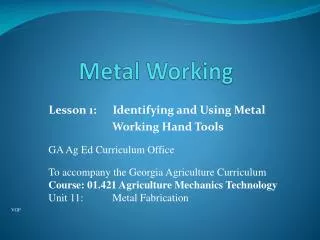
CHAPTER 5 METAL WORKING PROCESSES
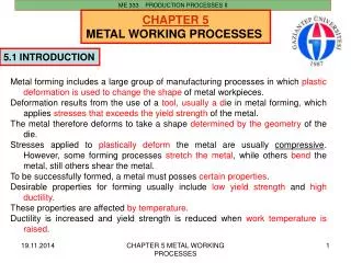
ME 333 PRODUCTION PROCESSES II. CHAPTER 5 METAL WORKING PROCESSES. 5 . 1 INTRODUCTION. Metal forming includes a large group of manufacturing processes in which plastic deformation is used to change the shape of metal workpieces.

CHAPTER 5 METAL WORKING PROCESSES
E N D
Presentation Transcript
ME 333 PRODUCTION PROCESSES II CHAPTER 5 METAL WORKING PROCESSES 5.1INTRODUCTION Metal forming includes a large group of manufacturing processes in which plastic deformation is used to change the shape of metal workpieces. Deformation results from the use of a tool, usually a die in metal forming, which applies stresses that exceeds the yield strength of the metal. The metal therefore deforms to take a shape determined by the geometry of the die. Stresses applied to plastically deform the metal are usually compressive. However, some forming processes stretch the metal, while others bend the metal, still others shear the metal. To be successfully formed, a metal must posses certain properties. Desirable properties for forming usually include low yield strength and high ductility. These properties are affected by temperature. Ductility is increased and yield strength is reduced when work temperature is raised. CHAPTER 5 METAL WORKING PROCESSES
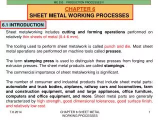
ME 333 PRODUCTION PROCESSES II 5.1.1 DEFINITIONS Plastic Deformation Processes Operations that induce shape changes on the workpiece by plastic deformation under forces applied by various tools and dies. Bulk Deformation Processes These processes involve large amount of plastic deformation. The cross-section of workpiece changes without volume change. The ratio cross-section area/volume is small. For most operations, hot or warm working conditions are preferred although some operations are carried out at room temperature. Sheet-Forming Processes In sheet metalworking operations, the cross-section of workpiece does not change—the material is only subjected to shape changes. The ratio cross-section area/volume is very high. Sheet metalworking operations are performed on thin (less than 6 mm) sheets, strips or coils of metal by means of a set of tools called punch and die on machine tools called stamping presses. They are always performed as cold working operations. CHAPTER 5 METAL WORKING PROCESSES
ME 333 PRODUCTION PROCESSES II 5.1.2Material considerations Material Behavior In the plastic region, the metal behavior is expressed by the flow curve: σ = Κεn Where; Kis the strength coefficient and n is the strain-hardening (or work- hardening) exponent. K and n are given in the tables of material properties or are calculated from the material testing curves. Flow stress For some metalworking calculations, the flow stressσf of the work material (the instantaneous value of stress required to continue deforming the metal) must be known: σf = Κεn CHAPTER 5 METAL WORKING PROCESSES
ME 333 PRODUCTION PROCESSES II Average (mean) flow stress In some cases, analysis is based not on the instantaneous flow stress, but on an average value over the strain-stress curve from the beginning of strain to the final (maximum) value that occurs during deformation: σf = Κεn Fig. 5.1 Stress-strain curve indicating location of average flowstressf in relation to yield strength y and final flowstress f. CHAPTER 5 METAL WORKING PROCESSES
ME 333 PRODUCTION PROCESSES II The mean flow stress is defined as: here εf is the maximum strain value during deformation. Work-hardening It is an important material characteristic since it determines both the properties of the workpiece andprocess power. It could be removed by annealing. Work hardening, also known as strain hardening or cold working, is the strengthening of a metal by plastic deformation. This strengthening occurs because of dislocation movements within the crystal structure of the material. Any material with a reasonably high melting point such as metals and alloys can be strengthened in this fashion. CHAPTER 5 METAL WORKING PROCESSES
ME 333 PRODUCTION PROCESSES II 5.1.3Temperature in metal forming The flow curve is valid for an ambient work temperature. For any material, K and n depend on temperature, and therefore material properties are changed with the work temperature: Fig. 5.2 True stress-strain curve showing decrease in strengthcoefficient K and strain-hardening exponent n withwork temperature CHAPTER 5 METAL WORKING PROCESSES
ME 333 PRODUCTION PROCESSES II There are three temperature ranges-cold, warm & hot working: Fig. 5.3 Temperature range for different metal formingoperations. TA is the ambient (room) temperature,and Tm is the work metal meltingtemperature CHAPTER 5 METAL WORKING PROCESSES
ME 333 PRODUCTION PROCESSES II Metal forming processes can also be classified according to the working temperature. The effect of temperature gives the rise to distinctions between cold working, warm working, and hot working. Hot and cold working of metals is of great importance in engineering production. Processes such as forging, rolling, drawing and extrusion predominate in the primary stages of production and have been perfected through developments. Hot Workingis the initial step in the mechanical working of most metals and alloys. Hot working reduces the energy required to deform the metal. It also increases ability of metals to flow without cracking. However, due to high temperature, surface oxidation and decarburisation can not be prevented. Cold Workingof a metal results in an increase in strength or hardness and a decrease in ductility. But, when cold working is excessive, the metal will fracture before final size has been reached (<0.3Tm). Hot Working of metals takes place above the recrystallization temperature. Cold Working must be done below the recrystallization range (0.5Tm to 0.75Tm). CHAPTER 5 METAL WORKING PROCESSES
ME 333 PRODUCTION PROCESSES II Cold workingis metal forming performed at room temperature. Advantages:better accuracy, better surface finish, high strength and hardness of the part, noheating is required. Disadvantages:higher forces and power, limitations to the amount of forming, additionalannealing for some material is required, and some material are not capable ofcold working. Warm workingis metal forming at temperatures above the room temperature but below therecrystallization one. Advantages: lower forces and power, more complex part shapes, no annealing is required. Disadvantages:some investment in furnaces is needed. CHAPTER 5 METAL WORKING PROCESSES
ME 333 PRODUCTION PROCESSES II Hot workinginvolves deformation of preheated material at temperatures above the re-crystallizationtemperature. Advantages:big amount of forming is possible, lower forces and power are required, formingof materials with low ductility, no work hardening and therefore, no additionalannealing is required. Disadvantages:lower accuracy and surface finish, higher production cost, and shorter tool life. CHAPTER 5 METAL WORKING PROCESSES
ME 333 PRODUCTION PROCESSES II 5.1.4Friction effects Homogeneous Deformation If a solid cylindrical workpiece is placed between two flat platens and an applied load P is increased untilthe stress reaches the flow stress of the material then its height will be reduced from initial value of hoto h1. Under ideal homogeneous condition in absence of friction between platens and work, any heightreduction causes a uniform increase in diameter and area from original area of Ao to final area Af. The load required, i.e. the press capacity, is defined by; Fig. 5.4Homogeneous deformation CHAPTER 5 METAL WORKING PROCESSES
ME 333 PRODUCTION PROCESSES II Inhomogeneous deformation In practice, the friction between platens and workpiece cannot be avoided and the latter develops a“barrel” shape. This is called inhomogeneous deformation and changes the load estimation as follows: where μ is the frictional coefficient between workpiece and platen. Fig. 5.5Inhomogeneous deformation withbarreling of the workpiece CHAPTER 5 METAL WORKING PROCESSES
ME 333 PRODUCTION PROCESSES II Metal forming processes can be classified as: 1. Bulk deformation processes: Forging, Rolling, Extrusion and Drawing (wire); 2. Sheet metalworking processes: Bending, Drawing (cup, deep), Shearing Fig. 5.6 Typical metal-working operations CHAPTER 5 METAL WORKING PROCESSES
ME 333 PRODUCTION PROCESSES II h0 hf Flash (çapak) Flash Gutter (çapak haznesi) A0h0 = Afhf Closed die forging Open die forging 5.2 FORGING Forging is the working of metal into a useful shape by hammering or pressing. It is the oldest of the metal working processes. Most forging operations are carried out hot, although certain metals may be cold forged. The two broad categories of forging processes are open-die forgingand closed-die forging. Closed-die forging uses carefully machined matching die blocks to produce forging to close dimensional tolerances. Fig. 5.7Forging processes CHAPTER 5 METAL WORKING PROCESSES
ME 333 PRODUCTION PROCESSES II • According tothe degree to which the flow of the metal is constrained by the dies there are three types of forging: • Open-die forging • Impression-die forging • Flashless forging Fig. 5.8 Three types of forging: (a) open-die forging, (b) impression die forging, and (c) flashless forging CHAPTER 5 METAL WORKING PROCESSES
ME 333 PRODUCTION PROCESSES II Open-die forging Known as upsetting, it involves compression of a work between two flat dies, or platens. Force calculationswere discussed earlier. Fig.5.9 Sequence in open-die forging illustrating theunrestrained flow of material. Note the barrel shapethat forms due to friction and inhomogeneousdeformation in the work Fig. 5.10 Open-die forging of a multi diameter shaft CHAPTER 5 METAL WORKING PROCESSES
ME 333 PRODUCTION PROCESSES II Impression-die forging In impression-die forging, some of the material flows radially outward toform a flash: Fig. 5.11 Schematics of the impression-die forging process showingpartial die filling at the beginning of flash formation inthe center sketch, and the final shape with flash in theright-hand sketch Fig. 5.12 Stages (from bottom to top) inthe formation of a crankshaft byhot impression-die forging CHAPTER 5 METAL WORKING PROCESSES
ME 333 PRODUCTION PROCESSES II Flashless forging The work material is completely surrounded by the die cavity during compression and no flash isformed: Fig. 13 Flashless forging: (1) just before initial contact with the workpiece, (2) partial compression, and (3) final push and die closure. Symbol v indicates motion, and F - applied force. Most important requirement in flashless forging is that the work volume must equal the space in the die cavity to a very close tolerance. CHAPTER 5 METAL WORKING PROCESSES
ME 333 PRODUCTION PROCESSES II Coining Special application of flashless forging in which fine detail in the die are impressed into the top andbottom surfaces of the workpiece. There is a little flow of metal in coining. Fig.14 Coining operation: (1) start of cycle,(2) compression stroke, and (3) ejectionof finished part CHAPTER 5 METAL WORKING PROCESSES
ME 333 PRODUCTION PROCESSES II Raising Rollers PE = m g h = W h Upper Die Lower Die W 5.2.1 FORGING EQUIPMENT • Forging equipment may be classified with respect to the principle of operation: • Forging hammers (Şahmerdan): • The force is supplied by a falling weight. These are energy-restricted machines since the deformation results from dissipating the kinetic energy of the ram. Their capacity is expressed with energy units. Fig. 5.15 Drop forging hammer CHAPTER 5 METAL WORKING PROCESSES
ME 333 PRODUCTION PROCESSES II Pressurized oil WW b) Mechanical forging presses are stroke-restricted machines since the length of stroke and available load at positions of stroke represent their capacity. Their capacity is expressed with load. c) Hydraulic presses are load restricted due to pressure in oil. Their capacity is expressed with load. Fig. 5.16 Hydraulic press CHAPTER 5 METAL WORKING PROCESSES
ME 333 PRODUCTION PROCESSES II Fig. 5.17Drop forging hammer, fed by conveyor and heating unit at the right of the scene. CHAPTER 5 METAL WORKING PROCESSES
ME 333 PRODUCTION PROCESSES II Stroke W Load (P) o 5.2.2 FORGING LOAD • In determination forging load for free upsetting (open die), two assumptions can be made for simplicity: • Material is perfectly plastic • No friction between material and die surfaces. CHAPTER 5 METAL WORKING PROCESSES
ME 333 PRODUCTION PROCESSES II and where P: forging load (press force) A: area and o: flow strength The work done CHAPTER 5 METAL WORKING PROCESSES
ME 333 PRODUCTION PROCESSES II If there is friction: Schey Equation For Closed die forging AT: total cross sectional area and c1 = 1.2-2.5 for open die forging c1 = 3.0-8.0 for simple shape closed die forging c1 = 8.0-12.0 for complex shape closed die forging CHAPTER 5 METAL WORKING PROCESSES
ME 333 PRODUCTION PROCESSES II 5.3. ROLLING Rolling is a metal deformation process where the thickness of the metal is reduced by successive passes from rolls. Fig.18 The process of flat rolling CHAPTER 5 METAL WORKING PROCESSES
ME 333 PRODUCTION PROCESSES II The metal emerges from the rolls traveling at the higher speed than it enters or CHAPTER 5 METAL WORKING PROCESSES
ME 333 PRODUCTION PROCESSES II Flat Rolling Fig. 19 Side view of flat rolling and the velocity diagram indicating work and rollvelocities along the contact length L CHAPTER 5 METAL WORKING PROCESSES
ME 333 PRODUCTION PROCESSES II Fig. 5.20-a Various configurations of rolling mills CHAPTER 5 METAL WORKING PROCESSES
ME 333 PRODUCTION PROCESSES II Fig. 5.20-b Various configurations of rolling mills CHAPTER 5 METAL WORKING PROCESSES
ME 333 PRODUCTION PROCESSES II 5.3.1 STEEL ROLLING • Rolling into intermediate shapes-blooms, billets, slabs. • Processing blooms, billets, slabs into plates, sheets, bar stock, foils. • Steel is cast into ingots. Theare storedy in that shape. When milling is necessary, ingots are heated in soaking pits, up to 1200oC. Ingots are rolled into intermediate shapes: A bloom has a square section above 150x150 mm. A billet is smaller than a bloom with square section from 40x40 mm up to bloom. Slabs have a rectangular section with min. width 250 mm and min. thickness 40 mm. The strips are rolled from slabs. Steps in rolling The preheated at 1200oC cast ingot (the process is known as soaking) is rolled into one of the three intermediate shapes called blooms, slabs, or billets. * Bloom has a square cross section of 150/150 mm or more * Slab (40/250 mm or more) is rolled from an ingot or a bloom * Billet (40/40 mm or more) is rolled from a bloom CHAPTER 5 METAL WORKING PROCESSES
These intermediate shapes are then rolled into different products as illustrated in the figure: Fig. 5.21 Production steps in rolling CHAPTER 5 METAL WORKING PROCESSES
ME 333 PRODUCTION PROCESSES II Shape rolling The work is deformed by a gradual reduction into a contoured crosssection (I-beams, L-beams,U-channels, rails, round, squire bars and rods, etc.). Ring rolling Thick-walled ring of small diameter is rolled into a thin-walled ring oflarger diameter: Fig. 5.22 Ring rolling used to reduce the wall thickness and increase the diameter of a ring CHAPTER 5 METAL WORKING PROCESSES
ME 333 PRODUCTION PROCESSES II Thread rolling Threads are formed on cylindrical parts by rolling them between two thread dies: Fig. 5.23 Thread rolling with flat dies CHAPTER 5 METAL WORKING PROCESSES
ME 333 PRODUCTION PROCESSES II Gear rolling Gear rolling is similar to thread rolling with three gears (tools) that form the gear profile on the work Fig. 5.24 Gear rolling between three gear roll tools CHAPTER 5 METAL WORKING PROCESSES
ME 333 PRODUCTION PROCESSES II 5.3.2 LIMITING ROLLING CONDITION Plain strain conditions are valid for rolling (i.e. no change in width of plate) and speed of neutral plane (N) is equal to tangential speed of rolls: b hovo = b hf vf = b h vb: width CHAPTER 5 METAL WORKING PROCESSES
ME 333 PRODUCTION PROCESSES II The angle between the entrance plane and the centerline of the rolls is called angle of contact or angle of bite. For the workpiece to enter into the gap between the rolls, horizontal component of the normal force Pr and the frictional force F should be equal or frictional force should be bigger. where limiting condition for rolling. CHAPTER 5 METAL WORKING PROCESSES
ME 333 PRODUCTION PROCESSES II 5.3.3 ROLLING FORCE • The following parameters should be considered in rolling force calculations: • The roll diameter • Flow strength of material which is affected by strain rate and temperature • Friction between rolls and the work piece • The presence of front and/or back tension and R: radius of rolls, hm: mean thickness between entry and exit, and h: reduction in thickness. CHAPTER 5 METAL WORKING PROCESSES
ME 333 PRODUCTION PROCESSES II 5.3.4 ROLLING CALCULATIONS Volume Volume rate CHAPTER 5 METAL WORKING PROCESSES
ME 333 PRODUCTION PROCESSES II There is a point where which is called no-slip point or neutral point. Before and after this point slipping and friction occur between roll and workpiece. The amount of the slip can be measured by means of the forward slip: The reduction ratio sometimes used as draft In practice max. draft: (i.e. μ=0 no draft) μ: coefficient of friction R: roll radius μ ~ 0.1 0.2 0.4 cold warm hot CHAPTER 5 METAL WORKING PROCESSES
ME 333 PRODUCTION PROCESSES II Length of contact: Power: θ: angle of contact (rad.) on each roll N: rotational speed of roll Force: two rolls : average flow stress w : width Torque: CHAPTER 5 METAL WORKING PROCESSES
ME 333 PRODUCTION PROCESSES II Example: A 300x25 mm strip is fed through a rolling mill with two powered rolls each of 250 mm radius. The work thickness is to be reduced to 22 mm in one pass at a roll speed of 50 rpm. The flow stress of work material is 180 MPa and the coefficient of friction between roll and work is about 0.12. Determine if the friction is sufficient to permit rolling operation to be accomplished. If so calculate the roll force, torque and horsepower. for limiting rolling conditions feasible CHAPTER 5 METAL WORKING PROCESSES
ME 333 PRODUCTION PROCESSES II OR draft feasible CHAPTER 5 METAL WORKING PROCESSES
ME 333 PRODUCTION PROCESSES II 5.4 EXTRUSION Extrusion is a Bulk Deformation Process in which the work is forced to flow through a die opening toproduce a desired cross-sectional shape. Extrusion is the process by which a block of metal is reduced in cross-section by forging it to flow through a die under pressure. In general, extrusion is used to produce cylindrical bars or hollow tubes, but irregular cross-sections may also be produced. Lead, tin, aluminum alloys can be cold extruded. Horizontal type presses are used. Speed is depends on temperature and type of material used. Fig. 5.25 Typical shapes produced by extrusion CHAPTER 5 METAL WORKING PROCESSES
ME 333 PRODUCTION PROCESSES II 5.4.1 EXTRUSION TYPES • Extrusion is performed in different ways therefore different classifications are available: • Direct and indirect extrusion • Hot and cold extrusion • Continuous and discrete extrusion Fig. 5.26 Direct extrusion to produce hollow or semihollowcross section CHAPTER 5 METAL WORKING PROCESSES
ME 333 PRODUCTION PROCESSES II Direct extrusion Fig. 5.27Direct extrusion to produce solidcross section. Schematic shows the various equipmentcomponents. CHAPTER 5 METAL WORKING PROCESSES
ME 333 PRODUCTION PROCESSES II Indirect extrusion Fig. 5.28In indirect extrusion (backward, inverse extrusion) the material flows in the direction opposite to the motion of the ram to produce a solid (left) or a hollow cross section (right) CHAPTER 5 METAL WORKING PROCESSES
ME 333 PRODUCTION PROCESSES II 5.4.2 EXTRUSION FORCE AND ENERGY Fig. 5.29Ram pressure vs ram stroke CHAPTER 5 METAL WORKING PROCESSES
ME 333 PRODUCTION PROCESSES II Df hf ho It can be calculated similar to forging. Here, ram power and ram force are: and CHAPTER 5 METAL WORKING PROCESSES
ME 333 PRODUCTION PROCESSES II 5.5 WIRE DRAWING Drawing operation involves pulling a metal through a die by means of a tensile force applied to the exit side. The end is grasped by tongs on a draw bench and pulled through. There may be few successive drawing dies on continuous drawing. Wire and Bar Drawing is a Bulk Deformation Process in which the cross-section of a bar, rod or wire isreduced by pulling it through a die opening, as in the next figure: Fig. 5.30Drawing of a rod, bar, or wire CHAPTER 5 METAL WORKING PROCESSES