Download
1 / 26
260 likes | 536 Vues
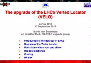
The upgrade of the LHCb Vertex Locator (VELO) Vertex 2013 17 September 2013 Martin van Beuzekom on behalf of the LHCb VELO upgrade group. Introduction to the upgrade of LHCb Upgrade of the Vertex Locator Radiation environment and silicon Readout challenge Cooling RF-box.

E N D
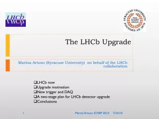
The upgrade of the LHCb Vertex Locator (VELO)Vertex 201317 September 2013Martin van Beuzekom on behalf of the LHCb VELO upgrade group • Introduction to the upgrade of LHCb • Upgrade of the Vertex Locator • Radiation environment and silicon • Readout challenge • Cooling • RF-box
Introduction to LHCb • Forward detector designed to search for New Physics by studying CP violation and rare decays of beauty and charm particles at the LHC • Excellent vertex & momentum resolution, particle ID and flexible triggering • 2 < η < 5 • ~30 % of heavy quark production x-section with 4% of solid angle ATLAS & CMS |η|< 2.5 ~10m 10 – 250 mrad LHCb 2 < η < 5 10– 300 mrad ~20m Martin van Beuzekom
Why upgrade • No deviation observed from The Standard Model (not yet) • -> Need more statistics! • Currently LHCb runs at twice its design luminosity • further increase is not possible (next slides) • At long shutdown 2 (2018) we hope to have ~3 x the current statistics • Another factor 2 in statistics will take another 5 years • not very rewarding • The amount of data and the physics yield from data recorded by the current LHCb experiment is limited by the detector • LHCb luminosity is lower than LHC can deliver, no LHC upgrade required • -> Upgrade the detector to cope with higher luminosity Martin van Beuzekom
Timeline long shutdown 1 long shutdown 2 50 ns 25 ns 25 ns Start-up 2010 2011 2012 2013 2014 2015 2016 2017 2018 2019 … 20xx LHCb Upgrade √s (TeV): 0.9 - 7 - 8 - 13 -14 L (cm-2s-1): 1032 3-4x1032 4x103210 – 20 x1032 5-7 fb-1 > 50 fb-1 3 fb-1 http://cds.cern.ch/record/1333091/files/LHCC-I-018.pdf http://cds.cern.ch/record/1443882/files/LHCB-TDR-012.pdf Martin van Beuzekom
Limitations of current detector • Main limitation is the 1 MHz readout of front-end electronics • First level (L0) trigger based on calorimeter and muon systems • Keeping < 1 MHz triggers at higher lumi means increasing thresholds • bottleneck for hadronic channels only • Saturation of trigger yield in hadronic final states at L = 4 x 1032 cm-2 s-1 • And also current detector not designed for higher lumi -> faster aging To benefit from high luminosity: • remove L0 bottleneck • read-out full detector at 40 MHz • ~30 MHz of colliding bunches • use fully software trigger Martin van Beuzekom
Trigger/DAQ • Remove first level hardware trigger -> gain a factor 5 in luminosity • Data from every bunch crossing sent to CPU farm • improves the yield of the hadronic channels • Total gain is > 10 50000 20 kHz Martin van Beuzekom
Changes to LHCb Upstream tracker: New strip sensors/modules (Outer) Tracker: New Scintillating Fiber tracker Muon System: Remove M1 See next talk by Nicola Neri VELO: New pixel sensors/modules M1 All: replace front-end electronics RICH: replace HPDs redesign mirrors (RICH1) Calorimeters: Remove SPD/PS Reduce HV & PM gain Martin van Beuzekom
Changes to Vertex Locator Performance of new VELO should be at least as good as current VELO • From micro-strips to pixels • pixels give fast pattern recognition; essential for the trigger • Thin sensors and thinned readout chips to minimize material • First active element at 5.1 mm from beam (was 8.2 mm) • Track rate (and radiation damage) will be 10x higher • Read out data from every bunch crossing -> challeng • CO2 Cooling of sensor modules with micro-channels etched in silicon • New RF-box Martin van Beuzekom
VELO upgrade • Full detector consists of 26 stations • 1 station = 2 modules, one on either side of the beam • varying spacing in beam direction, min. 24 mm between stations • total active area 1237 cm2 (= size of A3 sheet of paper) • Geometrical efficiency > 99 % for R < 10 mm • 99 % of tracks from interaction region have 4 or more hits ~ 1 m LHCb Martin van Beuzekom
Silicon module • Sensor tiles: 3 readout VeloPixASICs on a sensor: • 55 x 55 mm2 pixels • elongated pixels between ASICs • ~450 mm guard ring • 4 sensor tiles, 2 on each side of substrate • power and readout traces on kapton circuit board • Whole VELO ~41 Mpixels • Silicon substrate with integrated micro-channels for cooling • Material in active region ~ 0.8 % X0 ~43mm ~15mm Top Sensor 200 mm ASIC sensor Cooling In/outlets ASIC Micro channels 200 mm x 120 mm ...................................... ASIC 200 mm ASIC Si Substrate 400mm ....................... ............... Glue 50mm sensor ASIC glue Bot Sensor 200 mm ASIC200 mm Martin van Beuzekom
Radiation environment • After 50 fb-1 the tip of the sensor (at 5.1 mm) has received a fluence of 8x10¹⁵ 1 MeV neqcm-2 • We expect currents of ~200 mA/cm2 @ -20 °C and Vbias= 1000 V • =7 nA per pixel • power per sensor tile 130 mW @ 1000 V Integrated radiation dose / fb-1 Severe & non-uniform irradiation damage. 0.5 Radius [cm] • 200 mm silicon irradiated at these levels still gives a signal of ~ 8 ke- / MIP • half of the signal of an unirradiated sensor Martin van Beuzekom
Silicon sensors • Planar silicon, n-in-n or n-in-p to be decided • Tile for 3 VeloPix chips: ~ 43 x 14 mm, thickness 200 mm • 55x55 mm2 pixels, elongated pixels at ASIC boundaries, 2 x as large • Non homogeneous irradiation sets constraints on guard ring design • factor ~40 difference in fluence from tip to far corner • bias voltage at end on life ~1000 Volts for tip, far corner only at 2 x 10¹⁴neq • guard ring width ~450 mm • Final prototypes with 2 vendors (early 2014) • select from Micron/Hamamatsu/CNM d Dicing distances= 250μm, 400μm, 600μm Distance calculated from the active area. One/ two guard ring. CNM. Martin van Beuzekom
Velopix ASIC • Matrix of 256 x 256 pixels -> 14.08 x 14.08 mm2 active area • VeloPix is based on Timepix-3 (from Medipix-3 collaboration) • VeloPix designed by CERN medipix group and Nikhef • TPX3 is a general purpose chip • Many aspects of the design driven by VELO upgrade requirements • Re-use of MPX3 IP blocks, and use of CERN high density cell library • Chip testing started 2 weeks ago • 130 nm CMOS technology • Many specifications of TPX3 are the same/similar for VeloPix • Fast front-end: Timewalk < 25 ns • Simultaneous Time-of-Arrival and Time-over-Threshold measurements • Zero suppressed data • Trigger-less / data driven readout: Each hit is time-stamped, labeled and sent off chip immediately • Velopixhit-rate = ~8 x Timepix3 rate Martin van Beuzekom
Timepix-3 • 130 nm CMOS, 8 metal layers, 170 M transistors • designed by CERN with contributions from Nikhef and Bonn university • Chip back since 2 weeks • 2 chips mounted: 1 @CERN and 1 @Nikhef • Powered: “no smoke” ! • Periphery 95% tested and working • 8 serial output links running at 640 Mbit/s • Test of matrix ongoing • SPIDR readout using Xilinx Virtex-7 FPGA Martin van Beuzekom
A first glimpse of the Timepix-3 • Thanks to the Medipix-3 collaboration for releasing these results. • Very preliminary results! threshold scan for different trim DAC settings, single pixel • Equalisation of pixel matrix • Not (yet) calibrated • Much more to come soon • Medipix week • TWEPP, IEEE-NSS • Stay tuned! Martin van Beuzekom
VeloPix track rates & radiation • Assume 2400 out of 3600 bunches are colliding(26.7 MHz) • -> Average number of interactions per collision = 7.6 • Non-uniform occupancy, large variation in average rate from chip to chip • Average # particles / chip / event • event = colliding bunch • average (peak) rate: multiply by 26.8 (40) MHz • Hottest chip 8.5*26.8 (40) = 230 (320) Mtrack/s • => ~600 (890) Mhits/s per chip Radiation levels: • Order of 400 MRadin 10 year life time • Rad. tolerance demonstrated for this 130 nm technology Martin van Beuzekom
Timepix-3 -> VeloPix • Increase hit rate capabilities by factor 8 • grouping of pixel hits (2x4 super pixels) -> 30 % data reduction • increase output bandwidth • optimize buffering • Output bandwidth of VeloPix > 13 Gbit/s (average, 20 Gbit/s peak) • 4 links at ~ 5 Gbit/s • Single event upset robustness • DICE cells, 3-redundant • Comply to LHCbslow and fast control requirements • < 3 Watts per chip @ 1.5V (1.5 W/cm2) • Expected threshold ~1 ke- • Design is ongoing, same design team as Timepix-3 • Aim for first submission early summer 2014 • Production of chips end 2015 Martin van Beuzekom
Data acquisition overview • Data volume of whole VELO ~2.5 Tbit/s • LHCb common DAQ boards (TELL40) • ATCA standard • 4 mezzanines with powerful FPGA • 24 optical links in, max. 12 x 10 Gigabit Ethernet out • Electrical to optical conversion outside of vacuum tank • Lower radiation level • Easier accessible TELL40 (ATCA) max. 24 optical links FPGA differential copper links max. 24 optical links FPGA vacuumfeedthrough electrical -> optical CPU farm vacuumfeedtrhough max. 24 optical links differential copper links FPGA max. 24 optical links FPGA ~1 m ~60 m Martin van Beuzekom
Gigabit copper links in vacuum • Must be radhard, low outgassing, flexible • Using DupontPyralux AP-plus ‘kapton’ • Specially designed for HF applications • Measurements compared to simulations with 3D ADS momentum simulator • Transmission looks promising for 0.5 -1 m of cable but mechanically rigid Eye diagram for 100 cm length Martin van Beuzekom
TELL40 • One Stratix-V device for 24 optical links • Data out of VeloPix is not ordered in time • latency up to 250 clock cycles (@ 40 MHz) • Time re-ordering + sorting is resource intensive • What processing can we achieve • Reduce load on the CPU farm • Collecting/grouping all hits of a cluster • Grouping of hits in VeloPix in fixed 2x4 group • Many clusters will cross super-pixel boundary • Algorithm being developed • Clustering (centre-of-gravity) • Not yet clear what cost/benefit ratio is Event reconstruction TELL40 VeloPix • Packet receiver • Time ordering • Event buffering • Packet decoding Martin van Beuzekom
Micro-channel cooling • High speed pixel readout chips produce a lot of heat (~ 1.5 W/cm2) • Keep the sensors at < -20 °C to minimize the effects of radiation damage, and to avoid thermal runaway • Bring the cooling power where you need it, using least material • Novel method: evaporate CO2 via micro-channels etched in Si substrate • Additional advantages: no CTE difference (Si on Si) and very good uniformity of material in sensitive region Top Sensor 200 mm Cooling In/outlets Micro channels 200 mm x 120 mm ...................................... ASIC 200 mm Si Substrate 400mm ....................... ............... Glue 50mm cooling substrate retracted to reduce material budget at tip Bot Sensor 200 mm ASIC200 mm Martin van Beuzekom
Micro channel cooling II • Channel dimensions 200 x 120 mm2 • Pressure ~15 Bar at -30 °C, and ~60 Bar at room temp. • Including safety limits it has to withstand > 150 Bar • Detectors in vacuum, hence leakage/breakage is a very serious concern • Samples with hydrophobic bonding withstand > 700 Bar • Thermal and pressure cycling tests (-40 .. +40 °C, 0 .. 200 Bar) ongoing Inlet hole (Ø 2mm) example: not LHCb First prototypes (early2012) Transition from input restrictions (60 um width) to cooling channel (200mm). Output manifold with “pillars” 50 mm Martin van Beuzekom
Cooling result • Total power max. 40 Watts per module • Tests on half size prototype • Low DT at max. power • allowed DT < 15 °C “uch3” pt100 ~ 5 mm overhang Inner sensor + asics “uch2” pt100 “uch1” pt100 Outer sensor + asics Cooling substrate Glued surface: 11,34 cm2 CO2 connector More info on LHCb CO2 cooling by Eddy Jans (VELO experience) Thu 14:30 and Paolo Petagna (past & future) Thu 14:00 Martin van Beuzekom
RF-box Requirements • Electrically conductive: guides beam mirror current, shields EM wakefields • Vacuum tight: separates detector volume from beam volume • leakage < 10-9 mbar l/s • Low mass, dominates the X0 contribution before the 2ndmeasured point • Rigid, diff. pressure < 10 mbar during pump-down and venting of volumes • Aperture R=3.5 mm current VELO upgrade VELO NEG-coating RF-box Martin van Beuzekom
Milling of RF-box • Milling complete box from a solid block of Aluminium (118 x 27 x 27 cm3) • <300 mm thick top foil, 500 mm thick walls • Improvements being investigated • local chemical thinning with NaOH (after milling) • box from AlBeMet (~ factor 2 lower X0 for same thickness) ~ 30 % of final length Martin van Beuzekom
Conclusion / outlook • LHCb is actively working on a detector upgrade, to be installed in 2018 • Will run at L = 2 x 1033 (factor 5 increase w.r.t. current detector) • No more hardware trigger, all data to CPU farm • Vertex Locator will consist of planar silicon pixels, 55 x 55 mm2 • nearest pixel only 5.1 mm from the beams • fluence at tip of sensor 8x10¹⁵ 1 MeV neq / cm2 • VeloPix ASIC based on Timepix-3 • 130 nm CMOS, 20 Gbit/s output bandwidth per ASIC • Evaporative CO2 cooling in Silicon micro-channel substrate • low mass, small DT • < 300 mm thick RF-box milled from solid block of Aluminium The LHCb VELO upgrade is a very challenging project which uses many novel techniques Martin van Beuzekom