Download
1 / 30
300 likes | 435 Vues
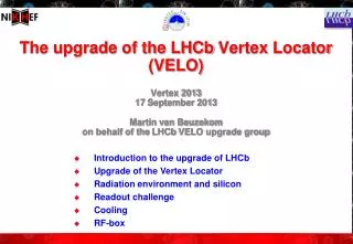
Performance of the LHCb Vertex Locator. Thomas Latham (on behalf of the LHCb VELO group). Introduction to LHCb. LHCb is a dedicated experiment for flavour physics at the LHC, in particular: Study of CP violation in beauty and charm decays Search for New Physics in loop processes

E N D
Performance of theLHCb Vertex Locator Thomas Latham (on behalf of the LHCb VELO group) TIPP 2011 - Chicago
Introduction to LHCb • LHCb is a dedicated experiment for flavour physics at the LHC, in particular: • Study of CP violation in beauty and charm decays • Search for New Physics in loop processes • Complementary to direct searches at ATLAS and CMS Detector requirements: • Efficient trigger for leptonic and hadronic final states • Excellent vertex finding ability • Extremely good tracking efficiency and particle identification TIPP 2011 - Chicago
The LHCb detector LHCb σ(pp → Hb X) = ( 75 ± 5 ± 13 ) µb Phys. Lett. B 694, 209-216 (2010) Interaction Point in the VELO Angular acceptance: 15 mrad < θ < 250 mrad TIPP 2011 - Chicago
The Role of the VELO • b-hadrons have lifetime of O(10-12)s • Relativistic boost means average flight distance of ~1cm • VELO has to precisely locate both primary and secondary vertices • Forms essential part of higher level trigger • Also a principal tracking device TIPP 2011 - Chicago
VELO Design • 2 retractable detector halves TIPP 2011 - Chicago
VELO Design • 2 retractable detector halves TIPP 2011 - Chicago
VELO Design • 2 retractable detector halves • 21 modules (+ 2 pile-up) per half • Each module has r and φ sensor • Detectors in secondary vacuum TIPP 2011 - Chicago
VELO Design • 2 retractable detector halves • 21 modules (+ 2 pile-up) per half • Each module has r and φ sensor • Detectors in secondary vacuum • Separated from LHC vacuum by 300µm foil • Foil also guards against RF pickup from beam TIPP 2011 - Chicago
Sensor Design • 2 semi-circular sensor designs • r and φ measuring • 300µm n-on-n silicon • 2048 strips per sensor • 8.2mm inner radius of active silicon • Cooled by evaporative CO2 system • Operating temperature of -30°C TIPP 2011 - Chicago
VELO Views Beam-eye view of open VELO VELO modules Close-up of RF foil TIPP 2011 - Chicago
VELO Performance! TIPP 2011 - Chicago
2011 Data ! Signal and Noise • Overall S/N as per design, > 20 • Noise on strips increases with strip length, hence with radius of r strips • Noise levels also differ between 3 different types of φ strips: • inner – routed over outer strips • outer – w/ overlaid routing lines • outer – no overlaid routing lines TIPP 2011 - Chicago
Spatial Alignment • VELO moved for each LHC injection • Precise knowledge of alignment critical for lifetime measurements • Proceeds in 3 stages: • Sensors within modules • Module to module within half • Inter-half alignment • Uses residuals from track fit • Module and sensor alignment known to better than 4µm • Inter-half stable over time to better than 5µm TIPP 2011 - Chicago
Hit Resolution • Measure residual of cluster to track made without that cluster • Correct for track uncertainty • Bin in both strip pitch and projected track angle • Best resolution < 4µm ! TIPP 2011 - Chicago
2011 Data ! Primary Vertex Resolution • Randomly split tracks into two sets • Fit two vertices and measure their separation • With 25 tracks per vertex: • x resolution = 13.1µm • y resolution = 12.5µm • z resolution = 71.1µm • Approaching design levels TIPP 2011 - Chicago
2011 Data ! Impact Parameter Resolution • IP = distance of closest approach of track to PV • Important variable for identifying long lived particles such as B mesons • Contributions from PV and hit resolutions plus multiple scattering • IP resolution improved with data based alignment • Some disagreement with simulation remains • Under investigation Preliminary TIPP 2011 - Chicago
Material Budget Total material budget 0.221X0 Material before 1st measurement 0.032X0 • Use detector model in simulation to estimate material budget TIPP 2011 - Chicago
Self Imaging • Use vertices of hadronic interactions with material to map VELO • Requires precise vertex measurements • Exactly what VELO was designed for! • Key features (sensors, RF foil etc.) stand out clearly • Preliminary comparisons between data and MC indicate good agreement TIPP 2011 - Chicago
New Results ! Velo Radiation Damage Studies Obtained from CCE vs Voltage • LHCbVELO HOT! • First Strip only 8mm from LHC beam • Outer strip 40mm • Maximum Fluence predicted at 14TeV • 1.3x10¹⁴ 1MeV neq/cm2/2 fb-1 • Strongly non-uniform • dependence on 1/r1.9and station (z) • Clear observation of radiation damage • IV, CCE, noise versus voltage Noise vs Voltage n-on-n sensor Annealed at 20 C over shutdown TIPP 2011 - Chicago
Summary • VELO has operated extremely well from day one • Operations becoming smoother over time • Performance is close to design parameters • Best hit resolution < 4µm – best at LHC! • Improvements already made based on 2010 data will reap further benefits for the LHCb physics programme this year • Outlook: • Still some room for improvements – work ongoing • Challenges to come from radiation damage • First evidence for radiation damage now seen • Replacement VELO under construction TIPP 2011 - Chicago
Backup TIPP 2011 - Chicago
Time Alignment • Nominal LHC bunch spacing 25ns • Fine tune timings of front end chips • Aim for • Maximum signal/noise • Minimum spillover • Sensors individually tuned to account for differences in • Time of flight • Cable length TIPP 2011 - Chicago
Cluster Finding Efficiency Only 1 bad chip out of 1344! • Efficiency generally extremely good • Most inefficiencies understood TIPP 2011 - Chicago
Middle station Far station • LHCbVELO HOT! TDR Prediction Velo Radiation Damage Studies • First Strip only 8mm from LHC beam • Outer strip 40mm • Maximum Fluence predicted at 14TeV • 1.3x10¹⁴ 1MeV neq/cm2/2 fb-1 • Strongly non-uniform • dependence on 1/r1.9and station (z) Tips of VELO sensors expected to type invert in next months of LHC running TIPP 2011 - Chicago
Velo Radiation Damage Monitoring Expectation: Depletion voltage of VELO sensors around 40-80V originally. Depletion voltage decreases with fluence till type inversion • Current vs applied bias Voltage (IV) • Taken weekly • Current increases with bulk damage, linearly related to fluence • Does not study depletion voltage • Noise vs applied bias Voltage • Taken monthly • Sensors decrease capacitance and hence noise when depleted, so sensitive to depletion voltage at least during early running • Charge Collection Efficiency vs applied bias voltage • Direct measure of physics relevant parameter • Can study rad. damage as function of position • Requires beam data so only taken a few times per year • April 2010 (~0), April 2011 (40 pb-1) TIPP 2011 - Chicago
IV Studies n-on-n sensor • Example sensors showing bulk damage Annealed at 20 C over shutdown • VELOn-on-n, contains one n-on-pmodule TIPP 2011 - Chicago
Noise vs Voltage • Measure voltage required to get noise to reduce by a specified fraction of the total depleted/undepleted change in noise Innermost strips on R sensor most irradiation Ratio < 1, i.e. change in V(noise min) Outermost strips on R sensor less irradiation Ratio ~ 1, i.e. no change in V (noise min) TIPP 2011 - Chicago
Charge Collection Efficiency (CCE) • Blue – tracking sensors – at full bias voltage • Red – test sensors – bias voltage ramped • 10V steps, 0V-150V • Rotate through patterns, fully automatic scan procedure • Tracks fitted through tracking sensors • Charge collected at intercept point on test sensors measured as function of voltage • Non-zero suppressed data taken so full charge recorded • Can study regions of sensor TIPP 2011 - Chicago
Charge Collection Efficiency (CCE) • Charge collection efficiency vs Voltage measured. • Voltage at which CCE is 80% extracted • 80% chosen as gives best agreement unirradiated with depletion • Here, averaged over all sensors, there is dependence of fluence on Z position • Region sizes chosen so that fluence varies by factor two in each region • Fluence expected to change as 1/r^{1.9} • Errors on plot are error on mean from all sensor average TIPP 2011 - Chicago
Same info. plotted for all regions, all modules • Lines are fits to all modules TIPP 2011 - Chicago