Download
1 / 21
230 likes | 422 Vues
Performance of Belle Silicon Vertex Detector. Masashi Hazumi (Osaka University, Japan). Outline. [1] Goal of Belle SVD [2] System Overview [3] Performance [4] Summary. [1] Goal of Belle SVD. Belle at KEKB. - Asymmetric Collider on (4S) -. e- 8GeV. e+ 3.5GeV. SVD. KEKB.

E N D
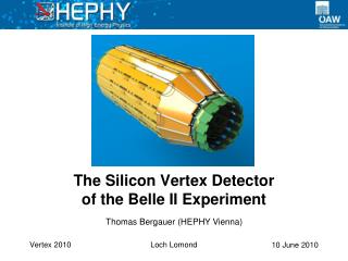
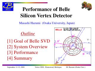
Performance of Belle Silicon Vertex Detector Masashi Hazumi (Osaka University, Japan) Outline [1] Goal of Belle SVD [2] System Overview [3] Performance [4] Summary Vertex 2000, Homestead, Michigan M. Hazumi (Osaka Univ.)
[1] Goal of Belle SVD Vertex 2000, Homestead, Michigan M. Hazumi (Osaka Univ.)
Belle at KEKB - Asymmetric Collider on (4S) - e- 8GeV e+ 3.5GeV SVD KEKB Vertex 2000, Homestead, Michigan M. Hazumi (Osaka Univ.)
Belle Collaboration SVD Group U. Hawaii Kanagawa U. KEK Krakow INP U. Melbourne National Taiwan U. Niigata U. Osaka U. Princeton U. U. Sydney U. Tokyo Tokyo Inst. Tech. Tokyo Metropolitan U. U. Tsukuba ~300 researchers (~50 institutes) from Australia, China, Germany, India, Korea, Japan, Philippines, Poland, Russia, Taiwan, Ukraine and USA Vertex 2000, Homestead, Michigan M. Hazumi (Osaka Univ.)
Physics Goal of Belle Observation of time-dependent CP asymmetry in B decays into CP eigenstates decay rate Δz=cβγΔt τB:B lifetime proper time difference t (ps) Vertex 2000, Homestead, Michigan M. Hazumi (Osaka Univ.)
Requirements on SVD • Good z resolution ~ 100m • multiple scattering is dominant • thin beampipe & svd • z strip pitch of ~80m is sufficient • good alignment should be pursued • High efficiency • good angular coverage (~90%) • good S/N ratio (~20) • small occupancy ( < 5%) • small readout deadtime ( less than 200s/event ) Vertex 2000, Homestead, Michigan M. Hazumi (Osaka Univ.)
[2] System Overview Vertex 2000, Homestead, Michigan M. Hazumi (Osaka Univ.)
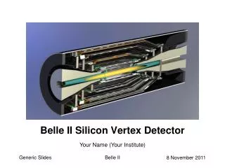
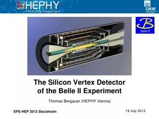
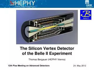
Detector Configuration • Be beampipe • r=20.0mm (inner surface) • double wall (500m thick/each wall) • 20m gold foil as X-ray absorber • Three layers of DSSD ladders (300m thick) • 1st layer r = 30.0 mm, 2 DSSDs in z, 8 ladders • 2nd layer 45.5 3 10 • 3rd layer 60.5 4 14 e- (8GeV/c) e+ (3.5GeV/c) 140° 23° 86% coverage Vertex 2000, Homestead, Michigan M. Hazumi (Osaka Univ.)
DSSD Ladders DSSD (S6936 manufactured by HPK) p-side (r) n-side (z) Active area 53.5×32.04 54.5×32.025 (mm2) Strip pitch 25 42 (μm) Readout pitch 50 84(μm) (ganged) # of readout 640 640 Only 2 kinds of half-ladders (“short” and “long”) “Long” half-ladder Bias Voltage 75V on n-side layer 1 : “short” + “short” layer 2 : “short” + “long” layer 3 : “long” + “long” p-n flipped Vertex 2000, Homestead, Michigan M. Hazumi (Osaka Univ.)
Readout Electronics Backend Electronics Frontend Electronics Vertex 2000, Homestead, Michigan M. Hazumi (Osaka Univ.)
Frontend Electronics VA1 (IDEAS, Norway) - rad. tolerant up to 200kRad (1.2m process) - excellent noise performance 200e- + 8e-/pF - Peaking time = 1s at Belle Vertex 2000, Homestead, Michigan M. Hazumi (Osaka Univ.)
Backend Electronics FADC (HALNY) • TTMs (Trigger Timing Modules) • Firmware-based flexible logic modules • Provide timing signals to FADCs and Repeaters • Control VA bias parameters • Issue (CAMAC-like) commands to repeaters • Monitoring, Gain measurement etc. etc. Vertex 2000, Homestead, Michigan M. Hazumi (Osaka Univ.)
[3] Performance Vertex 2000, Homestead, Michigan M. Hazumi (Osaka Univ.)
Strip yield and noise n-side • Strip yield1st layer 98.8%2nd layer 96.3%3rd layer 93.5% • Noisep-side 550e (S/N~35)n-side 1000e (S/N~19)p+n 1100e (S/N~17) • Cluster energyp-side 18.8ken-side 19.2ke p-side Vertex 2000, Homestead, Michigan M. Hazumi (Osaka Univ.)
Track Matching Efficiency • Probability that a track found in the drift chamber has associated SVD clusters • at least 2 layers • at least 1 layer with 2dim. information • Kalman filtering technique • Maching efficiency • Data : 98.7% (average) • MC : 98.7% • Stable (robust against beam background) Vertex 2000, Homestead, Michigan M. Hazumi (Osaka Univ.)
Impact Parameter Resolution 1) Z direction Real Data 36 42/psin5/2 [m] (Ideal) Monte Carlo 28 41/psin5/2 [m] Vertex 2000, Homestead, Michigan M. Hazumi (Osaka Univ.)
Impact Parameter Resolution 2) rdirection Real Data 19 50/psin3/2 [m] (Ideal) Monte Carlo 15 49/psin3/2 [m] Vertex 2000, Homestead, Michigan M. Hazumi (Osaka Univ.)
Signal Background z Resolution • Estimated with BD*l • (z) = 115 [m] +24 - 26 ( Liklihood fit tells you how the distribution is smeared with the finite resolution ) B lifetime, mixing and D lifetimes have been measured precisely. -> see ICHEP2000 web page Vertex 2000, Homestead, Michigan M. Hazumi (Osaka Univ.)
Time-dependent CP Asymmetry Belle Preliminary +0.07 - 0.09 (shown at ICHEP2000, Osaka) Belle SVD is working fine and is ready for the observation of time-dependent CP asymmetry ! Vertex 2000, Homestead, Michigan M. Hazumi (Osaka Univ.)
Belle SVD History and Upgrade Plan • SVD1.0 (Jan.1999-July.1999) • VA1 1.2m process • Good performance, but damaged by SR light • SVD1.2 (Aug.1999-July.2000) • Identical to SVD1.0, except beampipe with gold foil • OK till summer 2000 (~10% gain drop) • no guarantee for another year -> replaced • SVD1.4 (Aug.2000- July.2002) • Successfully installed • VA1 0.8m process : should be OK up to 1.2Mrad • Same configuration but smaller noise (atoll p-stop) • SVD2.0 (Aug.2002- ) • VA1 0.35m process : OK up to 20Mrad • smaller beampipe radius, 4 layers, shorter shaping time, etc. Vertex 2000, Homestead, Michigan M. Hazumi (Osaka Univ.)
[4] Summary • Belle SVD is working fine. • High S/N • High efficiency • CDC-SVD matching efficiency = 98.7% • Good impact parameter resolution • 36 42/psin5/2 [m] (z) • 19 50/psin3/2 [m] (r) • Good z resolution • (z) = 115 +24 -26 [m] • Radiation damage problem should be overcome. But we do have a good progress on this issue. • Upgrade with deep-submicron technology Vertex 2000, Homestead, Michigan M. Hazumi (Osaka Univ.)