Download

1 / 29
290 likes | 513 Vues
SVD (silicon vertex detector). 20 Feb. 2010 T. Tsuboyama (KEK) for the Belle2 SVD group. History and Overview. The Silicon vertex detectors for the present Belle have been operated since 1999.

E N D
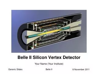
SVD (silicon vertex detector) 20 Feb. 2010 T. Tsuboyama (KEK)for the Belle2 SVD group
History and Overview • The Silicon vertex detectors for the present Belle have been operated since 1999. • Successfully accumulated 1 ab-1 data, or 1 billion of B meson pair production data, and contributed to establish the CP violation in the B meson decay. 20 Feb. 2010, T.Tsuboyama(KEK), Belle 2 SVD
Super KEKB factory • In order to explore the beyond-the-standard-model physics phenomena, a Super KEKB factory is proposed. • High precision measurement of the CKM matrix. • High statistics measurement of rare decay modes sensitive to new physics processes. • The luminosity goal is set at 8x1035/cm2/sec, 40 times higher than the present B factory. • In 10 years, data corresponding to 50 ab-1 will be accumulated. • Compared with the high-current scheme, the low-emittance scheme is beneficial to the vertex detector. • Smaller beam background and synchrotron radiation. • The radius of the beam pipe at the collision point is reduced from 15 mm to10 mm. 20 Feb. 2010, T.Tsuboyama(KEK), Belle 2 SVD
The Silicon vertex detector • The performance of Belle SVD2 was excellent. • The vertex detector with Silicon strip sensors works fine. • For Super KEKB, there are additional requirements. • About 30 times severe beam background is assumed. • Belle2 DAQ requests all sub detector system to work at 30 kHz trigger rate with negligible dead time. • DEPFET pixel detector (PXD) are used in the innermost layers. • Main SVD function is to extrapolate CDC tracks reliably to PXD. • Track information by SVD helps to reduce the data size of PXD significantly. • Self tracking capability of slow p± for the D* reconstruction. • SVD should be redesigned to satisfy these requirement 20 Feb. 2010, T.Tsuboyama(KEK), Belle 2 SVD
SVD in Belle2 • We keep the same name SVD or Strip Vertex Detector. • 4 layer of silicon strip detector ladders. • Readout with APV25 • Designed for CMS silicon strip tracker. • 50 nsec shaping time. • 192 stage analog pipeline. • Dead-time-less readout up to 32 readout queues. • Flexibility: All functions are programmable via I2C. • DSSDs from 6” wafers. • HPK restarted the DSSD production. • Test production in progress very carefully. • Prototype sensor will be delivered soon. 20 Feb. 2010, T.Tsuboyama(KEK), Belle 2 SVD
Sensor arrangement • The 4 layer detectors with coverage • 17 < q < 150: Full detector acceptance of Belle2. • 4 cm < R < 14 cm: Linking between PXD and CDC. • In the forward region, sensors are slanted (trapezoidal). • Thinner material • Smaller cluster size. • Slightly difficult mechanics. 20 Feb. 2010, T.Tsuboyama(KEK), Belle 2 SVD
Readout chips on DSSD sensor • Because of very tight space for readout electronics, the readout chips are place on the DSSD sensors. • To be discussed later. M. Friedl 20 Feb. 2010, T.Tsuboyama(KEK), Belle 2 SVD
Expected performance • The vertex resolution is determined by the PIXEL layer, closest to the collision point. • The sensor arrangement of SVD is determined with the Ks reconstruction capability for the B meson decay modes such as B K*0g. • If the Layer 6 is put at R=14 cm, R(layer 5)=12 is best. Reconstructed events Figure of merit 20 Feb. 2010, T.Tsuboyama(KEK), Belle 2 SVD
DSSD sensors • We submitted 2 types of DSSD • HPK restarted DSSD production 2009 August. • Arectangular sensor (124.9x59.6x0.32 mm2). • The first batch will arrive in March. • Preliminary tests indicates the production is going well. (HPK) 20 Feb. 2010, T.Tsuboyama(KEK), Belle 2 SVD
DSSD sensors • We submitted 2 types of DSSD • Micron: Trapezoidal (124.9x(59.6/40.4)x0.28 mm3) • Detail design with test structures by HEPHY Vienna. T. Bergauer, M.Valentan 20 Feb. 2010, T.Tsuboyama(KEK), Belle 2 SVD
DSSD stragegy • Prototypes of HPK and Micron sensor will be delivered soon. • Evaluation will be done in 0.5 years. • Thesensor production should be started in this fiscal year according to the evaluation result. 20 Feb. 2010, T.Tsuboyama(KEK), Belle 2 SVD
SVD data acquisition chain Finesse Transmitter Board (FTB) To pixel readout 19022m ~10 m FADC Unified data Link(> 20m) APV25 copper cable copper cable Boards Chips COPPER Trigger/timing distributor 195Origami Junction box Data sparsification, Common DSSD flex circuit No repeater Clustering and Receiver Sensors functions Hit time reconstruction Finesse 20 Feb. 2010, T.Tsuboyama(KEK), Belle 2 SVD
APV25 • Fast low-noise preamplifier tpeak=50 nsec • 192 stage ring buffer (Analog pipeline) • 32-cell readout queue. • 6-cell readout for “hit-time reconstruction” • hit time resolution << 5 nsec. • beneficial to reduce the hit occupancy • Rad hard > 10 M rad. C. Irmler 20 Feb. 2010, T.Tsuboyama(KEK), Belle 2 SVD
Origami Concept • Chip-on-sensor concept for double-sided readout • Flex fan-out pieces wrapped to opposite side (hence “Origami“) • All chips aligned on one side single cooling pipe Side View (below) M. Friedl 20 Feb. 2010, T.Tsuboyama(KEK), Belle 2 SVD
Origami prototype • Concept test has been done successfully. 20 Feb. 2010, T.Tsuboyama(KEK), Belle 2 SVD
Origami summary • Origami Module: • Successfully built the first Origami Module Prototype • Module has shown excellent performance at the beam test • Design of 6” Origami hybrid has been started recently • We build a complete ladder of the outermost SVD layer next year • Cooling: • SNR can be improved by ~20% using liquids @ sub-zero temperatures • Thin pipe: How can we ensure sufficient flow rate? • Common cooling system for PXD and SVD? • Hybrid cables: • Cables with ~8.7m tested tolerable SNR decrease of ~3% • No cross-talk measured • Repeater can be placed outside the detector 20 Feb. 2010, T.Tsuboyama(KEK), Belle 2 SVD
FADC • 24 channels/board. (80 boards will be necessary.) • Signal from APV25 chips are directly connected. • Data processing is done by FPGAs on this board. • Common mode correction • Zero suppression • Cluster finding • Hit-time reconstruction • FADC crates will be located above the Belle2 structure. 20 Feb. 2010, T.Tsuboyama(KEK), Belle 2 SVD
FTB (Finesse Transmitter Board) • Purpose • Connect FADC and COPPER. • Timing/Trigger information receiver. • Distribute SVD hit information to PXD readout system. • Design is in progress in discussion with PXD and KEK DAQ group. W. Ostrowicz (Krakow) 20 Feb. 2010, T.Tsuboyama(KEK), Belle 2 SVD
Occupancy and data rate M.Friedl • Worst case scenario (30 kHz trigger, 6 samples, no reduction by hit-time finding) foreseen at the 8e35 luminosity. • Essentially scaling up from SVD2, we get these approximated numbers. • Total data rate for this scenario is about 3.5GB/sec =10 khits*30 kHz*6 cells*2 Bytes. • About 0.7 GB/sec with online reduction by hit-time finding. 20 Feb. 2010, T.Tsuboyama(KEK), Belle 2 SVD
Summary of DAQ • APV25 is still the best chip for Belle2 SVD. • Prototype Origami hybrid works fine and we know APV25 can drive 10-m long cables. • The driver/receivers are integrated to FADC. • Less components inside the Belle structure. • Data from FADC will be sent to E-hut using the Unified optical data link. • A transmitter card is in design. • 80 FADC modules 80 common data links • 20-80 COPPER boards depending on the SVD data rate and on the data transfer performance of the COPPER system. 20 Feb. 2010, T.Tsuboyama(KEK), Belle 2 SVD
Mechanics • Intense discussions with PXD and IP chamber group. • The Belle rotation is helpful but the tight space issue is not solved by rotation alone. S. Koike 20 Feb. 2010, T.Tsuboyama(KEK), Belle 2 SVD
A ladder design with Origami hybird • The two sensors at both ends are read out with normal double side hybrid. • The sensors in middle are read out with Origami hybrid. • The average material budget for the Origami design is 0.6% radiation length. (0.4 % with DSSD only). Origami hybrids Flex fan outs Trapezoidal Sensor Connector Fixture Rectangular DSSD sensors Support Ribs I. Gfall 20 Feb. 2010, T.Tsuboyama(KEK), Belle 2 SVD
A 3D modeling • The design is in progress by using modern tools in addition to the conventional 2D drawing tools. • Both of them are necessary to proceed the reliable mechanics. I. Gfall 20 Feb. 2010, T.Tsuboyama(KEK), Belle 2 SVD
Cooling • Issues • How to flow coolant liquid to the Origami cooling tubes. • The APV25 performance is 20 % improved below 0 oC. • Common cooling system with DEPFET will be useful. • R&D for cooling with pressured CO2 is starting • Pros. • CO2 absorbs huge heat in evaporation at constant temperature. • Less probability of corrosion compared with water cooling. • Cons. • High pressure itself is difficult and dangerous. • A hermetic heat insulation will be necessary. • Condensation of water in air at the detector exit. • Heat insulation among the vertex detector, IP chamber and CDC. 20 Feb. 2010, T.Tsuboyama(KEK), Belle 2 SVD
Other Items • Monitor and interlock • Experience of Belle SVD will be useful. • Fast and reliable radiation monitor by Diamond sensor. • Power supply • The APV25 output can be directly supplied to the ADC system, just outside of Belle2 structure. • The power for the repeater amplifiers is saved. • The power supply for the current SVD could be recycled in Belle2 SVD. • Software • Job list is prepared. 20 Feb. 2010, T.Tsuboyama(KEK), Belle 2 SVD
Collaborations • Design and R&D for SVD in Belle2 • Basic study Since 2003: HEPHY, KEK, TIT, Niigata, Osaka, Krakow, Tohoku, Kyungpook, Tata, Princeton, Ljubljana… • APV25 readout, hybrid, FADC (HEPHY) • DAQ (Krakow) • Ladder and Support (HEPHY, KEK) • DSSD sensor (HEPHY, KEK) • At the production stage, we need much more collaborations. • There are candidate institutions in the Belle1/2 collaboration: • Melbourne, Karlsruhe… • Full approval of the Super B project by Japanese Government would encourage their decision. 20 Feb. 2010, T.Tsuboyama(KEK), Belle 2 SVD
Cost • Minimum cost of major components • From experience of previous SVD system, 50 % for spares and contingency. 20 Feb. 2010, T.Tsuboyama(KEK), Belle 2 SVD
Schedule 2010 2011 2012 2013 • aaa DSSD production Ladder production Ladder mount Combine SVD+PXD+IP chamber System test Installation to Belle and tests 20 Feb. 2010, T.Tsuboyama(KEK), Belle 2 SVD
Summary • SVD is designed to meet the harsh background level and high event rate at the Super B factory. • Innermost 2 layers: DEPFET • 3-6 layer: DSSD+APV25 • Schedule • 2009 Test production of DSSD started in HPK and Micron. • 2010: Evaluation of DSSD and mechanical design • 2011: Ladder and Support production • 2012: Ladder mount • 2013: System test and installation to Belle2 • 2014: Commissioning with Super KEKB accelerator. 20 Feb. 2010, T.Tsuboyama(KEK), Belle 2 SVD