PHENIX Vertex Tracker
PHENIX Vertex Tracker. Atsushi Taketani for PHENIX collaboration RIKEN Nishina Center RIKEN Brookhaven Research Center. Over view of Vertex detector Physics Goal Detector detail and Status of Production Expected Performance Summary. Overview. 2008. Silicon Vertex Tracker VTX (2010)

PHENIX Vertex Tracker
E N D
Presentation Transcript
PHENIX Vertex Tracker Atsushi Taketani for PHENIX collaboration RIKEN Nishina Center RIKEN Brookhaven Research Center • Over view of Vertex detector • Physics Goal • Detector detail and Status of Production • Expected Performance • Summary
Overview 2008 Silicon Vertex Tracker VTX (2010) Forward Silicon Vertex Tracker FVTX (2011) Gluon polarization (DG/G) measurement with heavy flavorandg-jet correlation.
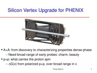
Silicon Vertex Tracker (VTX) • High spatial resolution : sDCA~ 100 mm 2p for f |h| < 1.2 Inner 2 layer : pixel detector Outer 2 layer : stripixel detector 4 layers barrel structure pixel full ladder stripixel full ladder 22.7cm 38.3cm • Large acceptance : |h| < 1.2, 2p for f pixel layer r=5.0cm Dz=±10cm r=2.5cm Dz=±10cm stripixel layer r=11.5cm Dz=±16cm r=16.5cm Dz=±19cm
Identifying heavy flavor production by VTX Simulation Background c quark b quark DCA (mm) pT (GeV/c) charm and beauty separation with difference of their life time e Life time (ct) D0 : 125 mm B0 : 464 mm D e + X B e + X DCA D p p B By simultaneous fitting the DCA distribution with the expected shapes, charm and beauty are separated. e Subtraction of background
Expected RAA(be) and RAA(ce) with VTX Strong suppression of single electrons from heavy flavor decay in Au+Au is one of the most surprising results in RUN4 The present measurement is mixture of be and ce VTX can separately measure RAA of be and ce Expected with VTX (0.4/nb ~3 weeks in RUN11) RUN4 Au+Au 200 GeV Au+Au 200 GeV PRL98,172301
Double Spin Asymmetry Direct g (pT(g), hg) Center of mass energy Center of mass energy Integrated Luminosity Integrated Luminosity ALL distribution as function of xg ALL distribution as function of pT PYTHIA Simulation (hjet) Jet Dg = g Simulation Simulation GRSV_std GRSV_std GRSV_std Dg = -g Dg = -g Dg = g L = 300 pb -1 L = 300 pb -1 P = 0.7 Dg = -g Dg = g P = 0.7 200mm < DCA pT (GeV/c) include backgrounds xg no backgrounds Heavy flavor measurement Gamma - jet correlation
Pixel Detector 57mm (32 x 4 pixel) 13mm 256 pixel 50mm x 425mm Sensor module Pixel bus SPRIO Pixel sensor modules Pixel stave (with cooling) Full ladder Pixel detector = inner 2 layers of VTX 1st layer: 10 full pixel ladders = 20 half ladders = 40 sensor modules 2nd layer: 20 full pixel ladders = 40 half ladders = 80 sensor modules ~4mm 7
PIXEL (Sensor and Readout) • Readout by ALICE_LHCB1 chip • Amp + Discriminator / channel • Bump bonded to each pixel • Running 10MHz clock ( RHIC 106nsec ) • Digital buffer for each channel > 4msec depth • Trigger capability > FAST OR logic for each crossing • 4 event buffer after L1 trigger Pixel size( x z)50 µm x 425 µm Sensor Thickness 200mm r = 1.28cm, z = 1.36 cm (Active area) 256 x 32 = 8192 channel / sensor 4 chip / sensor 4 sensor / stave
Pixel Readout Overview Bus Total < 60cm (70cm) Sensor 10cm Extender 60cm 11cm Half stave Bus (25cm ) + Extender (<35cm) 4*32 bit data bus is needed
Production has been started Assembletest Model Encapsulated Model Production model We have all pieces of parts Sensor modules Carbon staves Readout bus And Assembly technique. 6 ladder produced. Need 30 ladders. Electrically working well. Wired bonding and Encapsulation
1st Complete Pixel Ladder on Dec 25. All chips on Ladder #6 has good hit map by beta-ray source test
Strip detector 80mm x 30mm “stripixel” 80mm x 1mm pixel size (384 X + 384U strips) x 2 Stripixel sensor(Z. Li, BNL) 1 side, 2 direction read-out silicon module SVX4 Strip Ladder 128 ch/chip 8 bit ADC 5 (L3) or 6 (L4) silicon modules Read-out by 1 LDTB 1 sensor + ROC + 12 SVX4 Read-out by RCC board
Sensor elements: Two strip-pixel arrays on a single-sided wafer of 500 µm thickness, with 384 + 384 channels on 3 x 3 cm2 area. Initial design: “longitudinal” readout. Made by SINTEF Pixels: 80 µm 1 mm, projective readout via double metal XU/V “strips” of ~3 cm length. new design: “lateral” SVX4 readout. Made by Hamamatsu Stripixel layer Developed at BNL Instrumentation Gr. • Single sided • 1+1 dimensional readout ( X and U direction) • 768 X strip and 768 U strips/chip • 3cm x 3cm sensor x 2 / chip Position resolution is 25mm by test beam
Structure of Strip ladder Silicon module (ROC + Sensor + SVX4) Front-End Module (FEM) Stave Readout Control Chips (RCC) Bus Cable: Ladder-Data Transfer Board (LDTB)
Executive Summary I: - Silicon Module: assembly issues of the ROC-3 have been solved • Today:Pre-production (8 modules)3 silicon modules readout simultaneously • June 2008:One silicon module with ROC-3 ADC distributions corrected event-by-event pedestal subtraction Raw ADC distributions Raw ADC distributions Channel Number (128 channels x 12 chips) Channel Number (128 channels x 12 chips) Channel Number (128 channels x 12 chips) The silicon module gave good performance results starting mass production
Test beam at 120GeV Proton Stripixel FERMILAB Meson Test area 120 GeV Proton 5-30mm beam spot 4.5 sec spil per 1 min. 2×10¹⁰ proton / spil Pixel Proton Independent DAQ for Pixel and Stripixel. Using trigger scintillation counters Stripixel 3 Prototype ROC Trigger: Beam defining Scinti. DAQ : SVX4+ ROC+RCC Pixel 3 Prototype pixel ladder Trigger: Scinti * FAST_OR (3layer) DAQ: Prototype Readout + PHENIX DAQ
Pixel performance Residual Row direction Column direction count count Residual [mm] Residual [mm] sres = 57mm sres = 6.1mm Un-convolute Fit include all 3 layers hit position Multiple scattering effect Intrinsic resolution row : 14mm column : 152mm
Stripixel performance from Beam test result - Residual distribution (position resolution) • X-stripixel 0.42 x 80 (mm) = 33.6 (mm) • U-stripixel 0.44 x 80 (mm) = 35.2 (mm) - from the RMS values (tracks are defined by layers 1 and 3). - Tracking efficiency (detection efficiency) • X-stripixel: 99.5 +/- 0.2 % • U-stripixel: 98.9 +/- 0.2 % Tracking efficiency very good
Reconstructed [mm] True input of M.C. [mm] Expected Performance from GEANT DCA Comparison of Bottom -> e
Summary • PHENIX Vertex Tracker will be installed in 2010 and be operated from next RHIC. • VTX is capable to identify Charm and Bottom with fine spatial resolution and jet with larger geometry acceptance. • VTX will enhance physics capability in both spin and Heavy Ion program.