Download
1 / 14
140 likes | 166 Vues
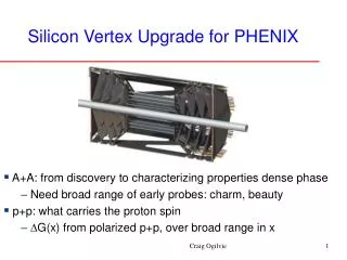
PHENIX Silicon Vertex Tracker. PHENIX Silicon Vertex Tracker. Mechanical Requirements Stability requirement, short and long 25 µm Low radiation length <0.5% Low CTE High stiffness-to-weight ratio Room temperature operation -- desirable Cooling – H2O desirable

E N D
PHENIX Silicon Vertex Tracker Mechanical Requirements Stability requirement, short and long 25 µm Low radiation length <0.5% Low CTE High stiffness-to-weight ratio Room temperature operation -- desirable Cooling – H2O desirable Kinematically mounted off Central Magnet
PHENIX Silicon Vertex Tracker Mechanical Specifications Central Barrel layer radius 2.5,6,8,10 cm layer length 30 cm pixel size 50 μm x 425 μm strips 80 μm x 3cm pixels( 1st layer) ~1.9M strips(2,3,4 layer) ~165k azimuthal coverage 320 deg End caps(each) inner radius 2.5 cm outer radius 18cm disk z position(at z= 2.5cm) 20,26,32,38 cm pixel size 50 μm x 4 mm total pixels ~2.0M azimuthal coverage 360 deg
PHENIX Silicon Vertex Tracker Simulated Performance Barrel occupancy 1st layer 1% 2nd layer 11.5% 3rd layer 7.2% 4th layer 4.8% resolution DCA <100 µm Endcaps occupancy all disks <3% resolution <100 µm
PHENIX Silicon Vertex Tracker Integration Designed to coexist with TPC < 20 cm radius. Clam shell design to fit around beam pipe. Radiation length ~ 1% per layer goal Barrel and end cap sections are separate units ( i.e. ATLAS type) Staging Option 1 Phase One --year 1 Design for barrel with strips first – no pixels or end caps Phase Two - after year 1 Second design for complete barrel and end caps Option 2 Design for barrel with option to add pixels, add end caps later
u u x x Silicon Strip Sensor N-type single-sided strip sensor developed by BNL (Z. Li) • Thickness : 400um (0.43 % X0), 250um (0.26% X0) for mass prod. • Size : 3cm*6cm, Pitch : 80um, 2-dim readout : x- and u-direction • #ch per sensor : 384 ch/dir * 4 dir =1536 ch Drawn by Yuji Goto
Prototype Sensor Module Prototype module development is on going. • Performance of the sensor will be tested w/ cosmic ray and beam at KEK. • Readout chip : VA2 (Viking 128 ch CMOS, analog multiplexer, 1us peaking time) Only this Draft
Toward Ladder Structurein Vertex Tracker • Barrel layer length: ~30cm • #chip : 12 readout chip/sensor • #sensor : 4 or 5 sensor/ladder • Cooling : dependent on readout chip Ex. SVX3D : 3.5mW/ch * 128ch/chip * 60sensor/ladder = 27 W/ladder Liquid cooling will be required. • Cabling : Cu(Al) / Polyimide hybrid for low material budget • Ladder material : ex. CFRP (Carbon Reinforced Polymer) • Total material budget goal : 1% X0 per layer
Mock-up of Barrel Support StructureMaterial : CFRP (Carbon-Fiber Reinforced Polymer) Precision, strength, deformation and material budget will be measured. Pictures and drawings : http://rarfaxp.riken.go.jp/~tojo/20020729/mockup20020729.htm
0 cm 50 ATLAS Vertex Detector • Support and cooling structures for ATLAS vertex detectors • Thermo-mechanical design • dimensional stability, low Z, high stiffness, heat removal capacity disks (10) center frame section end section (2) interior barrel layers internal end-cone (2) B-layer services
Prototype Frame During Fabrication Finished Prototype ATLAS: Support Frame • Support Frame End Section • All GFRP Construction • XN80/CE Facings • XN50/CE Honeycomb • High dimensional accuracy (<.001”) Load Test (Prism)
all carbon-carbon tube ~3.2 mm ID 0.25 mm wall thickness 10 cm 0 ATLAS: Silicon Detector Backplanes • Pixel detector support & cooling • Extreme stability ( < 10 µm @ -15ºC) • High heat flux (10,000 W/m2), active cooling circuit • Low mass ( < 2 kg/m2) • High stiffness ( > 100 Hz) tube extensions mounting points facing overhang