Download
1 / 20
200 likes | 373 Vues
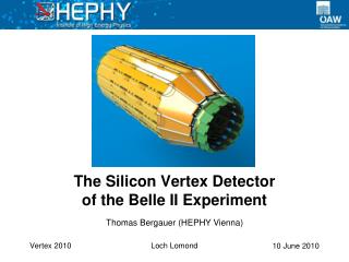
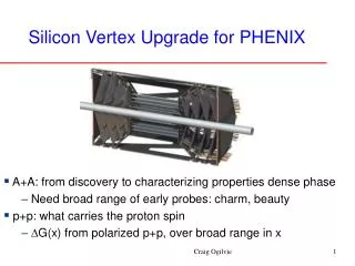
Mechanics and Assembly of the Silicon Vertex Detector for PHENIX. Walter Sondheim - LANL Mechanical Project Engineer; VTX & FVTX Detectors. PHENIX Experiment at RHIC:.

E N D
Mechanics and Assembly of the Silicon Vertex Detector for PHENIX Walter Sondheim - LANL Mechanical Project Engineer;VTX & FVTX Detectors TIPP Conference, June 10, 2011
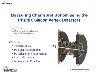
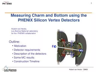
PHENIX Experiment at RHIC: The PHENIX experiment at RHIC is now in its 11th year of data taking. Experimental configuration for RUN in 2012: Vertex Region* 2 central arms; electrons, photons, hadrons 2 muon-spectrometer arms; muons *VTX installed for current run cycle, FVTX next year’s run cycle TIPP Conference, June 10, 2011
PHENIX Experiment at RHIC: 800.0 mm Available space for Vertex Detector 800.0 mm between the Central Magnet pole tips along the beam axis. The original 3.0 inch diameter Beryllium beam pipe was replaced with a 1.575 inch ID x .020 wall NEG coated Beryllium beam pipe, now installed for this run cycle. TIPP Conference, June 10, 2011
VTX Design Criteria: 440mm • VTX - Barrel Detector: • 2 pixel sensor layers at a radius = 25.0 and 50.0 mm • Fine granularity, low occupancy • 50µm x 450µm pixel size, ALICE LHCB1 read-out chip • AC Coupled read-out, required coolant temp. @ 10C • To avoidde-lamination • 2 stripixel layers at a radius = 100.0 and 140.0 mm • Unique sensor design from BNL Instrumentation • 80µm x 1000µm pixel pitch, SVX4 read-out chip • DC Coupled read-out, required cooling @ 0 C, • Avoid increase leakage current from radiation damage • acceptance ~ 2 • || acceptance < 1.2 • Dimensional structural stability to 25m Φ548mm Φ1000mm 800. mm TIPP Conference, June 10, 2011
VTX - Pixel layers 1 and 2: Total < 60cm (70cm) Bus Sensor 10cm Extender • Closest sensors to beampipe, radiation length should be kept to a minimum • Stave design uses Carbon composite technology, Omega shaped bonded to backside of thermal plane to create cooling channel. Bonded assembly must meet mechanical tolerance for flatness of 100. microns prior to bonding of sensor modules • Layers 1 & 2; 4 sensor modules per ladder, Layer 1 - 5 ladders layer 2 - 10 ladders per half barrel Assembled pixel stave: stave + sensors + readout chips + bus, readout is split in half – left bus and a right bus Omega shaped cooling tube; .504 mm thick, M55J, 8 ply .063 ply thickness PEEK mounting block Ground wire Assembled pixel stave with bus extender attached, interface with SPIRO readout card PEEK hose barb Thermal plane; 16.1 x 261.9 x .381 mm, M55J Graphite Cyanate Ester, 6 ply .063 ply thickness Bonding agent HYSOL EA9394 TIPP Conference, June 10, 2011
VTX - Stripixel layers 3 and 4: • Improve track segment construction • BNL sensor design provides 2 dimensional, single sided readout • Readout uses FNAL’s SVX4 chip; 128 channels per chip, 340K channels for layers 3 & 4 • Layer 3; 5 sensor modules per ladder, 8 ladder assemblies per half barrel • Layer 4; 6 sensor modules per ladder, 12 ladder assemblies per half barrel Sensor Module Sensors SVX4 chips Readout bus Layer 4 stave with sensor modules being located on stave using vacuum tooling, prior to bonding Interconnection between top layer and bus layer using PariPoser material TIPP Conference, June 10, 2011
Stripixel stave construction: Layer 3 & 4 stave assembly: designed to allow for individual electronic modules and bus to be mechanically attached to stave backside – not bonded. Aluminum rectangular cooling tube; 3.18 x 6.35 x .38 wall (mm) Face Sheets; K13D2U with EX1515 Cyanate Ester resin, .408mm thick, 6 ply layup, .063 ply thickness. Size for layer 3 – 319.8 x 36.1 mm, layer 4 – 383.5 x 36.1 mm* Aluminum end-block, grounds cooling tube PEEK pieces Carbon Foam Core; Allcomp K3, 4.2mm thick Bonding agent HYSOL EA9396 *Layer 3 stave shown in exploded view, assembly flatness tolerance 100. microns TIPP Conference, June 10, 2011
Thermal/Mechanical analysis: Pixel stave analysis • Thermal load for pixel stave is 19.50 watts • Each ladder’s mass summary: • Structure/Si-detector/Readout chips 16.4 grams • Coolant: 6.5 grams (3M-NOVEC 7200) • Total:23.0 grams • :11.5C* • :23.C with added metallic tube • Gravity sag < 2. microns • Pressure tested *Calculations using Nastran- Mat9 software Cross section Temperature profile, layer 4 ladder Stripixelstave analysis • Design goal to keep DC coupled sensors at 0C: • Coolant wall temperature at -6C • Peak temperature 3.2C • Temperature rise between coolant and sensor 5.55C Surface temperature, layer 4 ladder TIPP Conference, June 10, 2011
Space-frame and Barrel Mounts, exploded view: Main beam (2), POCO Graphite, extension attaches FVTX detector Stripixel layer 3 & 4 barrel mounts, M55J and Allcomp K3 Carbon foam, 6.3mm thick panel assembly Pixel layer 1 & 2 barrel mounts, M55J and Allcomp K3 Carbon foam, 3.6mm thick panel assembly Center gussets CN60 cloth, 2.mm thick Space frame shell, CN60 cloth with EX1515 resin, 1.5mm thick Space-frame flexure, 1 of 3 on each half TIPP Conference, June 10, 2011
Space-frame component fabrication and assembly: Space-frame shell tooling Space-frame shell: Vacuum jig machining cut-outs Layer 2 barrel mount on assembly jig All work at LBNL Composite Shop Layer 4 barrel mount on assembly jig TIPP Conference, June 10, 2011
FVTX detector: • Silicon tracking in the forward regions of PHENIX; • 1.2 < || < 2.4 • acceptance = 2 • Each FVTX assembly; • 4 tracking stations (Disks) • Silicon mini-strips, 2.8 – 11.2mm • 75. micron pitch (radial direction) • FPHX readout chip (FNAL design) • ~1.1M channels of readout FVTX detector exploded view from VTX assembly TIPP Conference, June 10, 2011
FVTX Station Disks: View of a Station Disk assembly with large Wedges attached to both sides Each Wedge covers 15 degrees, each sensor covers 7.5 degrees, Wedges on both sides of Disk staggered by 7.5 degrees front to back – hermetic coverage in phi Each disk assembly is pressure tested to 30. psi, cycled 5 times The disk assembly bonding agent was Hysol EA9396 TIPP Conference, June 10, 2011
LargeWedge construction: FPHX read-out-chips, 13 on each side of sensor, 128 channels each, 410. microwatts per channel, 1.36 watts/wedge Silicon sensor, 320. microns HDI, 334. microns Each wedge assembly is mounted to a station disk by 2 #2 screws and 2 locating pins Carbon back-plane, 1.56 mm, K13D2U with EX1515 resin Spacers – POCO graphite, AXM5Q, 2 versions of each low and high profile Separate ground connection point for Carbon Hirose DF18 series connector, 100 pin for large and 60 pin for small Hirose H.FL series mini-coax for bias TIPP Conference, June 10, 2011
Large Wedge analysis: • Thermal path for heat generated on large Wedge • Delta T on large Wedge is ~7.47 degrees C • Heat from FPHX chips passes through HDI into Carbon backplane – through POCO graphite thermal block to Station Disk where coolant flows around perimeter – NOVEC 7200 coolant • Delta T from Disk to Wedge ~ 8. degrees C • In analysis a temp constraint was set to keep peak FPHX chip temp at 21 degrees C • Bonding of all elements of Wedge assembly, made using Arclad 7876 transfer adhesive, 50. micron thick 23° 16.5° 12° 410 µW/Channel Base Temperature 13.53° C TIPP Conference, June 10, 2011
Station Disk construction, Stations 2, 3 & 4 Large Disk: R=182.0mm K13C2U uni-fiber face sheets, .40mm thick Carbon loaded PEEK cooling channel 3 holes for alignment flags around perimeter Mounting tab to Cage, one of three Carbon loaded PEEK pieces Hardware to mount and align Wedges to Disk Polyimide “bobbins” TIPP Conference, June 10, 2011
FVTX construction: FVTX cages and station disks being fabricated, tested and assembled at the LBNL composite shop. TIPP Conference, June 10, 2011
Metrology, FVTX wedge disk: One of 6 -100. micron cross-hair targets on Silicon wedge sensor used to verify relationship of sensors on a disk to 5.08 microns in X-Y and 12.27 microns in Z TIPP Conference, June 10, 2011
Metrology, Half VTX assembly: Half VTX assembly being optically surveyed: all ladders to global monuments in assembly. These will again be surveyed in relationship to monuments in the PHENIX hall. Expected detector positioning will be known to ~50. microns in the hall. TIPP Conference, June 10, 2011
CAD vs. As-Built: Demonstration of importance of constructing an accurate CAD model of experimental assemblies, installation of VTX proceeded just as modeled without any conflicts. TIPP Conference, June 10, 2011
VTX & FVTX collaboration institutions: • Brookhaven National Laboratory • Columbia University • Ecole-Polytechnique • Iowa State University • Kyoto University • Los Alamos National Laboratory • New Mexico State University • Oak Ridge National Laboratory • RIKEN • Riken-Brookhaven Research Center • Stony Brook University • University of New Mexico TIPP Conference, June 10, 2011