Download
1 / 25
250 likes | 441 Vues
École Polytechnique Fédérale de Lausanne. Liverpool University. Vrije Universiteit Amsterdam. LHCb Vertex Locator (VELO) Lars Eklund. Outline. Introduction to LHCb and VELO Design of the VELO Performance plots Towards a beam test in 2006 A more specific example:

E N D
École Polytechnique Fédérale de Lausanne Liverpool University Vrije Universiteit Amsterdam LHCb Vertex Locator (VELO)Lars Eklund
Outline • Introduction to LHCb and VELO • Design of the VELO • Performance plots • Towards a beam test in 2006 • A more specific example: • Digital filtering for x-talk corrections Lars Eklund, CERN
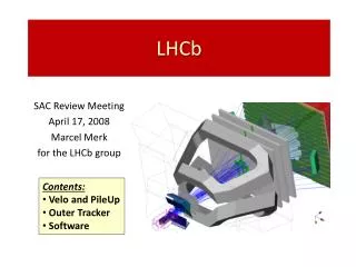
Angular acceptance 15 - 300mrad Tracker Trigger tracker Proton interaction region RICH 1 RICH 2 Magnet The Vertex Locator ECAL HCAL Muon chambers LHCb • Dedicated b-physics experiment at LHC • 1012 bb-pairs per year • CP violation and rare b-decays • Correlated boost of the bb-pairs • Single forward spectrometer Lars Eklund, CERN
,K Bs K K p Ds p Primary vertex bt Measurement of BS oscillations Since the oscillations are fast, it requires excellent vertex resolution VELO – the experimental challenge • Trigger on the B decay of interest (Velo part of software trigger) • Suppress multiple interactions (Pile-up veto part of hardware trigger) • Reconstruct decay as a function of time Lars Eklund, CERN
Downstream Interaction region Pile-up veto ~1m 2 backward stations in the H/W trigger The Vertex Locator (VELO) Minimalist view of the VELO • 21 Tracking stations • Four ½ disks sensors per station • Silicon micro-strip technology • R-Φ geometry • Minimise material • No conventional beam-pipe • Sensors are operated in vacuum • 250 μm Al foil to separate VELO from the beam vacuum • Minimise extrapolation distance • First active element at R = 8.2 mm • Retractable detector halves • 30 mm at LHC filling Lars Eklund, CERN
42 mm 8 mm FE chip F–measuring sensor (radial strips with an stereo angle) Velo Sensors R-measuring sensor (concentric strips) • n+ in n-bulk sensors • second metal layer for signal routing • 2048 micro strips per sensor • 40 – 100 μm pitch • Non uniform radiation environment • 1.3 * 1014 neq/cm2/year at R = 8 mm • 5 * 1012 neq/cm2/yearat R = 42 mm Lars Eklund, CERN
Silicon sensor Pitch adaptors Front-end chip (Beetle1.5) Cooling cookies Detector module PRR in December TPG/carbon fibre substrate with laminated kapton circuit Carbon fibre paddle Lars Eklund, CERN
Overspill vs. S/N cut Noise occupancy vs. S/N cut Cluster efficiency vs. S/N cut Results test beam November 2004 – 300 μm thick Φ measuring sensor Detector modules - performance • Operational window: • Sufficient cluster efficiency (> 99 %) • Acceptable noise occupancy (< 0.1 %) • Low fake cluster rate in next time bin (< 25 %) Lars Eklund, CERN
Secondary (detector) vacuum Detector halves retractable by 30 mm Primary (beam) vacuum RF foil (250 μm Al) CO2 cooling manifold Vacuum bellows (to allow the retraction) Cooling, vacuum and positioning Beam pipe Lars Eklund, CERN
Mechanics – status Vacuum and positioning assembly at NIKHEF Vacuum bellow Lars Eklund, CERN
Radiation dose: ~ MRad Radiation dose: ~100 kRad Radiation free area Radiation free area pre-compensating cable driver PC farm ADC and pre-processing FPGA 2 m low mass cable 60 m twisted pair readout network front-end ASIC DAQ chain • Kapton cables • low mass • flexible • vacuum compatible Cat 6 cable • Gigabit Ethernet • commercial components • Beetle 1.5 • analogue readout • 128 channels • 4 serial links • 900 ns readout time • Analogue repeaters • compensates cable response • COTS components • 5632 links • TELL1 • ADC (10 bit, 40 MHz) • digital filter • pedestal and common mode noise subtraction • strip re-ordering • clustering • PC farm • Linux cluster • software trigger • permanent storage Lars Eklund, CERN
dIP = 14mm+35mm/pT Bs vtx resolution (mm) Impact parameter resolution Performance Lars Eklund, CERN
Towards the final system… • Components are or will soon be in production • Module production will start in December 2005 • Assembly will start January 2006 • At CERN • System test April 2006 • Whole detector half powered and configured • 10 modules read out • Beam test 2006 • Whole detector half in the beam test • Fully system verification: Detector modules, control system, DAQ, reconstruction software, alignment … Lars Eklund, CERN
Two systems issues • Interaction vertices in the silicon sensors and halo tracks • Digital filtering of the analogue data link Lars Eklund, CERN
interaction in the sensor Partially commissioned at installation Test beam set-up scintilator trigger proton beam • Detector half operated in vacuum • Use silicon sensors as targets • Look for interactions in the silicon • Reconstruct tracks and align Lars Eklund, CERN
R [mm] Event display of an interaction in the silicon sensor. Tracks highly non-linear in the R-z plane z [mm] Need stand-alone tracking Tracks from interaction point (R=0) are linear in the R-z plane Pattern recognition assume tracks from close to R = 0 • Need for a stand-alone reconstruction package • Handles vertices anywhere • Feeds tracks to the alignment algorithm Lars Eklund, CERN
Velo Left Velo Right • Velo divided into four weakly coupled parts in terms of alignment: • Backward-Left, Backward-Right,Forward-Left and Forward-Right • very few tracks traverse more than one part L-B L-F R-B R-F Spin-off: halo tracks in LHCb cartoon event display of the VELO • Solution: Use beam halo tracks and interactions in the silicon sensors for alignment in LHCb • Re-use algorithms from the beam test 2006 Lars Eklund, CERN
Two systems issues • Halo tracks and interaction vertices in the silicon sensors • Digital filtering of the analogue data link Lars Eklund, CERN
Data is transferred on four serial links per front-end ASIC: signal noise 25 ns Blue: no signal (pedestals) Red: signal in two channels header 32 channels serial data (800 ns) Digital filtering – the problem • Signal travels through: • front-end hybrid • kapton cables (2 types) • vacuum feed-through • Amplifier (+ PCB) • 60 m TP cable Lars Eklund, CERN
H(z) G(z) x[n] w[n] y[n] Digital filter Sensor, ASIC and the analogue link Modelling the problem Consider each output as a number series, where n corresponds to the channel number x[n] : “True” data at the input (from sensor or test pulse) w[n] : Raw ADC values y[n] : Corrected values H : Transfer function of the ASIC and the analogue link G : Transfer function of the digital filter • Method:(Assuming LTI: Linear Time Invariant System) • Determine H from the data (from beam particles or calibration pulses) • Find ‘G’ such that G*H = 1, implying that y[n] = x[n] Lars Eklund, CERN
x-talk measurements from TB November 2004 h[+1] h[-1] 4 ASICs, 16 serial links: 32 different impulse responses The impulse response The transfer function H is characterised by the series h[n]: h[n] can be determined by injecting a single pulse: • Obtaining a Delta function δ: • Internal calibration pulses • Feature of the Beetle chip • From track data • Point a track on the sensor • Select tracks centered on strips • Assume no charge sharing • look at the signal in adjacent channels Lars Eklund, CERN
H(z) G(z) x[n] w[n] y[n] Digital filter Sensor, ASIC and the analogue link and requires that The infinite sum is truncated to M + N – 1 conditions: where Determining the filter algorithm (1) • Postulate: • The impulse response h[n] = 0, except for N time-bin • g[n] = 0, except for M time-bins (Finite Impulse Response filter = FIR). Lars Eklund, CERN
corrected x-talk from TB November 2004 4 ASICs, 16 serial links: 32 different impulse responses Determining the filter algorithm (2) • The truncated sum gives: • N + M – 1 constraints • M unknowns (the g[n]) Solve these over constrained equations with the least square method • Boundary problems: • 32 channels per link • exceptions for channels 0 and 31 • missing information • The data header • specific corrections Lars Eklund, CERN
Effects on the resolution Results test beam November 2004 – 200 μm thick R measuring sensor (7 degree track angle) • Track residuals: • reversed readout order for small radii • Asymmetric (forward/backward) x-talk • step in residuals • Resolution: • Smearing due to x-talk • Odd/even channel dependence • ~1 μm improvement Lars Eklund, CERN
Summary • The Vertex Locator of LHCb uses silicon micro-strip sensors with R-Φ geometry • Operated in vacuum with retractable detector halves • Shows good efficiency and noise occupancy performance in the beam test • Is in production – assembly will start soon • System issues • System test and beam test 2006 • Specific example • Corrections of the data link Lars Eklund, CERN