Chapter Three – Orthogonal projection
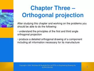
Chapter Three – Orthogonal projection. After studying this chapter and working on the problems you should be able to do the following: understand the principles of the first and third angle orthogonal projection

Chapter Three – Orthogonal projection
E N D
Presentation Transcript
Chapter Three –Orthogonal projection • After studying this chapter and working on the problems you should be able to do the following: • understand the principles of the first and third angle orthogonal projection • produce a detailed orthogonal drawing of a component including all information necessary for its manufacture Copyright 2001 McGraw-Hill Australia Pty Ltd PPTs t/a Engineering Drawing 6eby Bert Boundy
Figure 3.1 – Orientation of rear view Copyright 2001 McGraw-Hill Australia Pty Ltd PPTs t/a Engineering Drawing 6eby Bert Boundy
Figure 3.2 –Third-angle projection Copyright 2001 McGraw-Hill Australia Pty Ltd PPTs t/a Engineering Drawing 6eby Bert Boundy
Figure 3.3 – Choosing number of views Copyright 2001 McGraw-Hill Australia Pty Ltd PPTs t/a Engineering Drawing 6eby Bert Boundy
Figure 3.4 – Relationship of orthogonal views Copyright 2001 McGraw-Hill Australia Pty Ltd PPTs t/a Engineering Drawing 6eby Bert Boundy
Figure 3.5 – Methods of projections between views Copyright 2001 McGraw-Hill Australia Pty Ltd PPTs t/a Engineering Drawing 6eby Bert Boundy
Figure 3.6 – First-angle projection Copyright 2001 McGraw-Hill Australia Pty Ltd PPTs t/a Engineering Drawing 6eby Bert Boundy
Figure 3.7 Copyright 2001 McGraw-Hill Australia Pty Ltd PPTs t/a Engineering Drawing 6eby Bert Boundy
Figure 3.8 – Dimensions of working space Copyright 2001 McGraw-Hill Australia Pty Ltd PPTs t/a Engineering Drawing 6eby Bert Boundy
Figure 3.9 – Positioning of views Copyright 2001 McGraw-Hill Australia Pty Ltd PPTs t/a Engineering Drawing 6eby Bert Boundy
Figure 3.10 – Construction of views Copyright 2001 McGraw-Hill Australia Pty Ltd PPTs t/a Engineering Drawing 6eby Bert Boundy
Figure 3.11 – Complete view Copyright 2001 McGraw-Hill Australia Pty Ltd PPTs t/a Engineering Drawing 6eby Bert Boundy
Figure 3.12 – Principles of linear dimensioning Copyright 2001 McGraw-Hill Australia Pty Ltd PPTs t/a Engineering Drawing 6eby Bert Boundy
Figure 3.13 – Isometric view of a steel wall bracket Copyright 2001 McGraw-Hill Australia Pty Ltd PPTs t/a Engineering Drawing 6eby Bert Boundy
Figure 3.14 – Calculations for view positions Copyright 2001 McGraw-Hill Australia Pty Ltd PPTs t/a Engineering Drawing 6eby Bert Boundy
Figure 3.15 – Complete orthogonal projection Copyright 2001 McGraw-Hill Australia Pty Ltd PPTs t/a Engineering Drawing 6eby Bert Boundy