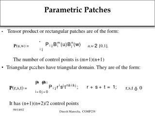
Parametric Devices
Parametric Devices. Uses non linear reactance or time varying reactance Parametric term is derived from parametric excitation, since the capacitance or inductance, which is a reactive parameter , can be used to produce capacitive or inductive excitation.


Parametric Devices
E N D
Presentation Transcript
Uses non linear reactance or time varying reactance Parametric term is derived from parametric excitation, since the capacitance or inductance, which is a reactive parameter, can be used to produce capacitive or inductive excitation. Parametric excitation is subdivided into parametric amplification and oscillation. Many of the essential properties of non linear energy storage systems were described by Faraday and Lord Rayleigh.
The first analysis of non linear capacitance was given by Van derZiel in 1948 which suggested that such a device might be useful as a low noise amplifier, since it was essentially a reactive device in which no thermal noise is generated. In 1949 Landon analyzed and presented experimental results of such circuits used as amplifiers, converters, and oscillators. In the age of solid state electronics, microwave electronics engineers thought of a solid state microwave device to replace the noisy electron beam amplifier.
In 1957 Suhl proposed a microwave solid state amplifier that used ferrite. The first realization of a microwave parametric amplifier was made by Weiss in 1957 after which the parametric amplifier was last discovered. At present the soild state varactor diode is the most widely used parametric amplifier. Unlike microwave tubes, transistors and lasers, the parametric diode is of reactive nature and thus generates a very small amount of Johnson (thermal) noise.
Parametric amplifier utilizes an ac rather than a dc power supply as microwave tubes do. In this respect, the parametric amplifier is analogous to the quantum amplifier laser or maser in which an ac power supply is used.
A reactance is defined as a circuit element that stores and releases electromagnetic energy as opposed to a resistance, which dissipates energy. If the stored energy is predominantly in the electric field, the reactance is said to be capacitive; inductive if in the magnetic field. C = Q/V If the ratio is not linear, the capacitive reactance is said to be nonlinear. In this case it is convenient to define a non linear capacitance as the partial derivative of charge with respect to voltage.
i.e C(v) = dQ/dt The analogous definition of non linear inductance is L(i) = dΦ/di. In the operation of parametric devices, the mixing effects occur when voltages at two or more different frequencies are impressed on a nonlinear reactance.
Derived a set of general energy relations regarding power flowing into and out of an ideal nonlinear reactance. These relations are useful in predicting whether power gain is possible in a parametric amplifier.
One signal generator and one pump generator at their respective frequencies , together with associated series resistances and bandpass filters, are applied to a nonlinear capacitance C(t). These resonating circuits of filters are designed to reject power at all frequencies other than their respective signal frequencies. In the presence of two applied frequencies an infinite number of resonant frequencies of are generated, where m and n are any integers.
Each of the resonating circuits is assumed to be ideal. The power loss by the nonlinear susceptance is negligible. That is the power entering the nonlinear capacitor at the pump frequency is equal to the power leaving the capacitor at the other frequencies through the nonlinear interaction. Manley and Rowe established the power relations between the input power at the frequencies and the output power at the other frequencies
It is assumed that the signal voltage vs is much smaller than the pumping voltage vp, and the total voltage across the nonlinear capacitance C(t) is given by The general expressionof the charge Q deposited on the capacitor is given by
For Q to be real, The total voltage v can be expressed as a function of the charge Q. A similar taylor series expression of v(Q) shows that V to be real,
The current flowing through C(t) is the total derivative of Q w r t time. Hence, Where
Since the capacitance C(t) is assumed to be pure reactance, the average power at the frequencies is Then conservation of power can be written
Multiply the above equation by a factor of and rearrangement of the resultant into two parts yield Since Then, Becomes, And is independent of ωp or ωs.
For any choice of the frequencies fp and fs, the resonating circuit external to thatof the nonlinear capacitance C(t) can be so adjusted that the currents may keep all the voltage amplitudes Unchanged. The charges are also unchanged, sincethey are functions of the voltages .
Consequently, the frequencies can be arbitrarily adjusted in order to require Eqn I can be expressed as
Since , then Similarly, Where are replaced by respectively.
The above equations are standard forms for the Manley-Rowe power relations. The term indicates the realpower flowing into or leaving the nonlinear capacitor at a frequency of . . The frequency represents the fundamental frequency of the pumping voltage oscillator and the frequency signifies the fundamental frequency of the signal voltage generator.
The sign convention for the power term will follow that power flowing into the nonlinear capacitance or the power coming from the two voltage generators is positive, whereas the power leaving from the nonlinear capacitance or the power flowing into the load resistance is negative. Consider for instance, the case where the power output flow is allowed at a frequency of as shown in fig.