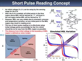
Lecture 3 Ultra-short pulse parametric devices
440 likes | 588 Vues
This lecture, presented by David Hanna from the Optoelectronics Research Centre at the University of Southampton, explores the fascinating world of ultra-short pulse parametric devices. It covers key topics such as synchronously pumped optical parametric oscillators (SPOPOs), optical parametric amplifiers (OPA), and their performance characteristics. The lecture highlights the advantages of parametric processes in the ultra-short pulse regime, including high gain, broad bandwidth, and wavelength flexibility. Additionally, it discusses challenges like energy storage and synchronization requirements, providing a thorough understanding of the latest advancements in this cutting-edge field.

Lecture 3 Ultra-short pulse parametric devices
E N D
Presentation Transcript
Lecture 3Ultra-short pulse parametric devices David Hanna Optoelectronics Research Centre University of Southampton Lectures at Friedrich Schiller University, Jena July/August 2006
Lecture Outline • General features and attractions of ultrashort pulse parametric devices • Synchronously Pumped OPOs (SPOPOs): general considerations • Specific examples of SPOPO performance • Optical Parametric Amplifiers (OPA), Optical Parametric Chirped Pulse Amplifiers (OPCPA) & Optical Parametric Generators (OPG) • Carrier Envelope Phase considerations
Attractions of parametric processes in the ultrashort pulse regime • High gain; damage intensity behaves ~1/(pulse duration)½ • Broad gain bandwidth • Wavelength flexibility (eg different from Ti:Sapphire!) • Reduced ASE, reduced background, good contrast • High Quantum efficiency • Low thermal effects • Good beam quality • Scalability
Some disadvantages of parametric processes • Small aperture dimensions available • No energy storage • Synchronisation requirements • High pump brightness required
Some general features of ultra-short pulse parametric devices • High gain and wide bandwidth can be obtained in a single pass of a parametric amplifier: lasers require regenerative amplification • For the shortest pulses, ensure a large enough gain-bandwidth + good temporal overlap between the interacting waves over the NL medium Short crystal length can ensure the above, but places limits on the achievable gain • Alternative ways to increase the gain bandwidth include: near-degenerate operation non-collinear phase-matching • Double refraction effects are reduced for shorter crystals • Non-collinear phase-matching can contribute to group-velocity-matching
Dependence of double-refraction effects on crystallength For a given double-refraction walk-off angle ρ, and beam diameter D, the effect of walk-off in a crystal of length is insignificant if ρL/D << 1 For confocal focussing, 2πw02n/λ = L, i.e., D = 2w0 = [2Lλ/nπ]½ so; ρL/D = ρ[πnL/2λ]½ Hence, for shorter crystals, as required for shorter pulses, confocal focussing is less compromised by double refraction 10x shorter pulse →10x shorter Xtal → tolerate√10x greater ρ value
Synchronously-pumped OPO > > Signal and idler output pulse train Mode-locked pump: pulse separation matches round trip of OPO N.L.Xtal > > > • OPO gain corresponds to the peak power of the pump pulse • Crystal length must be short enough so that group velocity dispersion does not separate pump, signal and idler pulses in the crystal.
SPOPO pump requirement versus crystal length If length L is determined by the allowable Group Delay Difference, then, L T and if confocal focussing is used, then, gain LP = LE/T E Hence, threshold is specified by an energy, independent of pulse duration, & for a given repetition rate, threshold average power is then independent of pulse duration. But Self Phase Modulation is more problematic for shorter pulses, since effect of SPM ( fractional spectral broadening) IL PL/L E/T (T,P,E,I are, respectively, pump pulse duration, power, energy, intensity)
Some Attractions of SPOPOs • Low threshold average power (amenable to diode pumping) • Power scalable, eg via fibre-pumped SPOPOs • Very wide tuning • Synchronised outputs at two wavelengths (e.g. for CARS) • Very high gain possible, can oscillate even with very high idler loss • Very high efficiency, e.g. makes the tandem OPO practical
SPOPO facts and figures • Average output power > 20 W • Shortest pulses 13 fs • Tuning range 0.45 – 9.7 micron • Efficiency (diode laser OPO) 25% • Slope efficiency >100% (170% observed)
Crystal length constraint for a SPOPO • Require enough signal gain bandwidth for a signal pulse duration ~ pump pulse duration T (away from degeneracy) Use higher order terms in Taylor expansion if the vg are nearly equal • Require signal (& idler) pulse not to walk away from pump pulse Signal case
How to tune a QPM OPO Angle tuning may not be an option, so: • Fixed pump; tune crystal temperature (fine tune) change grating period (coarse tune) • Tune pump wavelength • Fixed pump; tune across gain-bandwidth via intra-cavity filter, or diffraction grating reflector.
SPOPO slope efficiency of > 100% L.Lefort, et al., Optics Communications Vol.152 pp.55-58 (1998)
Order of magnitude pulse compression in a PPLN SPOPO 4ps pump, 250fs signal, 20mm PPLN ~100fs/mm pump/signal Group delay difference Lefort et al. Opt Letts, 24(1),28,1999
Other features of SPOPO • Cavity length change can change signal wavelength: not a good technique for tuning as pulse characteristics will change • Oscillation tolerates cavity length changes of many pulse widths. Stabilise cavity length via stabilising the output frequency • Tuning through the gain profile can lead to higher order transverse modes of the signal • Tuning elements involving angular dispersion, eg grating, produce tilted pulses • In QPM materials, many additional outputs may be seen (2ωs, 2ωi, ωs+ωp, ωi+ωp).
PPLN SPOPO with feedback via diffraction grating Tilted signal pulse is ‘cleaned up’ in PPLN amplifier before exiting the cavity Hanna et al J Phys D Appl Phys,34,2440, (2001)
Tilted pulses produced by diffraction grating From Hanna et al.J Phys D, Appl Phys., 34,2440, (2001)
CdSe tandem-pumped SPOPO M.A.Watson, M.V.O'Connor, D.P.Shepherd, D.C.Hanna Optics Letters 28 (20) pp.1957 (2003)
CdSe SPOPO Non-critical (θ = 90o ) type-II phase-matching curves in CdSe, for pump-wavelength tuning. The pump wavelength range has been limited at the long end to the signal range from the pump OPO and at the short end by twice the band gap wavelength, where two-photon absorption would become significant. Inset: diamonds indicate experimental idler tuning points. M.A.Watson, M.V.O'Connor, D.P.Shepherd, D.C.Hanna Optics Letters 28 (20) pp.1957 (2003)
Infrared absorption edge of Lithium Niobate Sato et al Appl. Optics 38, 2560, 1999
SPOPO with idler absorption (1) Signal gain, if small, is For large αL this is i.e. threshold is increased by αL/4 Lowenthal IEEE JQE, 34, 1356 (1998) Lefort et al APL, 73 (12), 1610 (1998) Watson et al Opt.Letts 27 (23), 2106 (2002)
SPOPO with idler absorption (2) Photon conversion efficiency to idler output: (D is pump depletion, R is signal round-trip loss) Output idler power is that generated in last extinction length of the crystal Strategy for efficient idler generation: Increase Ip until D~ 0.5 and make R as small as possible (eg use ring resonator). But avoid excessive (damaging) signal intensity M.A.Watson et al. A.P.L.73 (12), 2108,(2002)
SPOPO with idler absorption (3) M.A.Watson et al, Optics Letters Vol.27(23) pp.2106-8 (2002)
SPOPO pumped by femtosecond mode-locked fibre laser O’Connor et al Opt Letts., 27 (12), 1052, (2002)
High power femtosecond fibre feedback SPOPO 19W av o/p@ 1450nm, 7.8W @3570nm Südmeyer et al. Opt Letts. 29, 1111, (2004)
Fibre feedback SPOPO: insensitivity of output power to resonator length changes Südmeyer et al. Opt Letts., 29,1111,(2004)
Femtosecond (down to 13fs) visible OPOvia non-collinear phase-matching in BBO Gale et al. JOSA B, 15, 792, (1998)
Coupled NL equations for signal & idler in the pump pulse frame Gale et al. JOSA B 15, 792, (1998)
Non-collinearly phase-matched femtosecond OPA with a 2000cm-1 bandwidth Shirakawa and Kobayashi Appl. Phys. Letts., 72(2),147, 1998
Matching of group velocities by spatial walk-off in collinear three-wave interaction with tilted pulses Danielius et al., Opt. Letts., 21, 13, 973, (1996)
Pulse-front matched OPA for sub-10-fs pulse generation… Shirakawa et al. Opt. Letts., 23,16,1292, (1998)
Visible pulse compression to 4fs by OPA +programmable dispersion control Prism P3 imparts tilt (angular dispersion) to the SH (ie pump) beam Baltuska et al., Opt Letts., 27,306, (2002)
Visible compression to 4fs by OPA+ programmable dispersion control Dashed curve is for monochromatic pump. Inset shows spectrum of SH used as pump Baltuska et al., Opt. Letts., 27, 306, (2002)
Yet more OPA designs… • OPCPA +multiple pumps, at different wavelengths, to increase the gain bandwidth. Wang et al., Opt Commun., 237,169, (2004) • Use of chirped broadband pump + operation near degeneracy. Limpert et al., Opt. Express, 13, 19, 7386, (2005) • Ultrabroadband (octave-spanning) OPCPA, using angularly dispersed signal Arisholm et al., Opt. Express, 12, 518, (2004)
Efficiency-enhanced soliton OPA • Pump, signal and idler are mutually trapped in a spatial soliton • This requires a phase-mismatch whose ideal value depends on the mix of pump, signal and idler powers • These powers evolve through the amplifier, hence ideally one needs a longitudinally varying phase-mismatch through the medium • SOLUTION: Use aperiodic QPM medium Rodriguez et al JOSA B,19, 1396, (2002)
Tandem-chirped OPA grating design for simultaneous control of group delay and gain control • Chirped grating 1 produces idler with frequency-dependent group delay • Idler from grating 1 acts as signal for grating 2, hence idler from 2 has frequency of original signal • Grating 2 compensates group delay dispersion of grating 1 Charbonneau-Lefort et al., Opt. Letts., 30,634,(2005)
Cavity-enhanced OPCPA • Cavity acts as a reservoir and amplifier for the pump • Long pump pulse avoids cavity dispersion issues • Need to minimise optical Kerr effect in cavity Ilday & Kärtner, Opt . Letts.,31, 637, (2006)
Generation of few cycle terawatt light pulses via OPCPA CEP stabilised pulses from TiS oscillator maintain their CEP in OPA + compressor Witte et al., Opt. Express, 13, 4903, (2005)
Carrier Envelope Phase (CEP) • Carrier phase offset between carrier peak and envelope peak can vary from pulse to pulse • This has significant effects in high field experiments using few-cycle pulses Brabec and Krausz Rev. Mod. Phys., 72,545,2000
Self-stabilisation of CEP via parametric processes In an OPA, with signal only as input, the phase relation, φp-φs-φi = -π/2 , applies through the medium if Δk = 0 If the signal is derived from the pump, eg as in generation of supercontinuum, signal and pump have the same phase behaviour. So, using the pump to amplify this signal in an OPA leads to a CEP stable idler even if the pump is not CEP stable. If this CEP stable idler does not have the desired power it can be used as the input signal to a second amplifier, OPA2 Since this amplified signal has its phase preserved in OPA2 one now has a high power pulse that is CEP stable Baltuska et al., Phys Rev Letts. 88, 133901, (2002)
Generation of high energy self-phase-stabilised pulses via DFG and OPA DFG between spectral components of the supercontinuum produced in the fibre gives a CEP stable pulse whose stability is maintained in OPAs Manzoni et al. Opt Letts., 31, 963, (2006)
Concluding remarks • OPAs are widely seen as a preferred alternative to TiS for amplification of ultrashort pulses to high powers • Much needs to be done to establish power-scaling limits of OPOs, and OPAs. • Designs for OPAs are numerous and new proposals keep appearing. Not yet a mature field; work is in progress. • Different circumstances, e.g. pulse energy, duration, wavelength, call for different designs. Not a case of “one size fits all” • Numerical calculations need to include transverse effects. Plane-wave models are ignoring vital aspects