LANSCE Short-Pulse Target Operation
200 likes | 379 Vues
LANSCE Short-Pulse Target Operation. High-power Targetry for Future Accelerators September 11, June 2003 Richard Werbeck Los Alamos National Laboratory. Manuel Lujan Jr. Neutron Scattering Center. Proton Radiography. Proton Storage Ring. 800-MeV Linear Accelerator. Weapons

LANSCE Short-Pulse Target Operation
E N D
Presentation Transcript
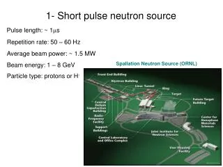
LANSCE Short-Pulse Target Operation High-power Targetry for Future Accelerators September 11, June 2003 Richard Werbeck Los Alamos National Laboratory
Manuel Lujan Jr. Neutron Scattering Center Proton Radiography Proton Storage Ring 800-MeV Linear Accelerator Weapons Neutron Research Future Isotope Production Facility Neutron Resonance Spectroscopy LANSCE Visitor’s Center The Los Alamos Neutron Science Center serves several scientific communities. APT Materials Irradiation
An overview of Line D, the PSR, 1L Target and ER-1 and 2. Proton Storage Ring Line D 1L Target ER-2
There have been four different targets for the Lujan short-pulse spallation source. • Mark 0a • Installed 1985 • Provided neutrons for 12 flight paths, flux-trap design • 3 water moderators, 1 liquid hydrogen moderator • Mark 0b • Installed 1991 • Rebuild of Mark 0a • Mark I • Installed 1998 • Major redesign: All TMRS components on a single insert • Provide neutrons for 16 flight paths • 4 water moderators, 2 liquid hydrogen moderators • Mark II • Installed 2002 • Same as Mark I except for upper target cooling manifoldand beryllium/stainless-steel reflectors
The target now serves 16 flight paths at the Lujan Center. 1998 2003
The 1997-1998 LANSCE reliability upgrade (Mark 1) had the following goals. • Add capability for more neutron beam lines • Provide upper tier moderators forfour new flight paths • Preserve performance of lower-tier moderators • 100 mA operation at 20 Hz • Design Target-Moderator-Reflector-System(TMRS) module for 200mA and 30 Hz • Beam availability > 85% • Target change in 2 to 3 weeks • Reliable support systems
Proton beam pipe Service connections Beam diagnostic& beam window Outer reflector Inner reflector Upper-tier cryo moderator Lower-tier flight-path liner Upper tungsten target Outer reflector Lower tungsten target The Mark I design had all of the major components on a single insert.
Target upgrade operations began in August 1997. • Remote handling removal operations took place in November and December of 1997. • New target components were still under construction while old components were being removed. • During final installation (July), the need for a nuclear authorization basis was discovered • The APT experiments on the 800kW proton line and the new target are Category 3 nuclear under DOE-STD-1027 • A credible mechanism for tungsten dispersion existed • A joint 1L / A6 BIO was prepared (DOE-STD-3009) • BIO submitted 24 Sep 1998 • SER issued 29 Sep 1998 • Contractor readiness assessment 28 Sep – 6 Oct 1998 • Pre-start findings closed on 21 Oct 1998
Commissioning of the Mark 1 target began in fall 1998. • Commissioning began on 25 October 1998 • 100mA (80kW) operation achieved on 19 Nov 1998 • Performance of new components was excellent • Performance of lower-tier moderators was preserved • Target cooling as expected • Corrosion was down by at least a factor of 50 • Many problems with legacy support systems • Reflector water-cooling system leaks • Hydrogen leaks and ice plugs • Contamination incidents (and other incidents) led to 1999 stand down
We used the 1999 outage was to improve legacy systems. • Water systems • “hand over hand” walkdown and documentation • formal procedures • compliance with ASME B31.3 • Hydrogen system • replace compression fittings with metal-gasket face-seal fittings • welded joints wherever possible • HVAC problems discovered during outage • pressure inversion observed at hot cell door • economy mode exchanged air between service area and occupied areas • no configuration control • deferred maintenance • unshielded HEPA filter bank
The radioactive drain system was also a serious problem. • Lack of ownership • drains partially plugged with concrete • no interface agreement with users • deferred maintenance • Major contamination incident (13 Oct 1999) • pressure release following pneumatic test • experimental areas contaminated with dust • mercury contamination was also detected • Corrective actions • formal procedures • all drains cleaned out • interface agreements
The new issues required a new AB and a DOE-led RA. • There were more controls required because of the HVAC issues • Serious confusion with A6 which was no longer running beam • DOE required ARF X RF = 1 • Previous incidents demanded more formality • DOE-led RA took place in March 2000 • Pre-start findings closed and permission to operate by 17 June 2000
2000 target operation was excellent. • Operated at nominal 100mA (80kW) • Availability was 97.3% for the target • 2.7% down time for gas removal • air separators not designed for gas production • Overall availability of 74.7% was due to problems with site power and RF systems.
2001 operations had high availability but reduced current. • The lower lead reflector suffered a loss of cooling capacity • temperature approached melting point of lead • beam current reduced to 55mA • The upper target developed an internal coolant flow anomaly • suspected internal weld failure • upper target flow is safety significant • Justification for Continued Operation (JCO) required • JCO established current limit of 75mA • Target performance • target 99.16%, Lujan Center overall 90.0%
Trend analysis of the upper target flow factor showed an increased conductance.
100 mm Several design problems were identified with the old upper target coolant passages. This weld on the inlet plenumcrosses other welds and joins pieces of differentthickness (suspected failure point) A weld failure in any of theseinternal welds will result inan internal shut that is notreadily detectable during operation This protrusion interferes with e-beam access to the inlet plenum weld
100 mm The design of the upper target coolant passages was changed to ensure a better weld preparation. Better weld prep on inletcooling plenum Inlet and outlet plena have beenseparated to eliminate thepossibility of an internal shunt Bottom of Inconel containerhas been shortened forbetter e-beam access to inletplenum weld
The TMRS insert was replaced in 2002 (Mark 2). • Most components were identical to the Mark 1 • Lead reflectors replaced • upper reflector changed to stainless steel • lower reflector changed to beryllium/stainless steel composite • The upper target manifold was redesigned • no possibility for internal shunt • better weld preparation • The target change operation will be discussed in another paper at this conference
2002 operations set a new record for beam current. • Operation at 125mA (100kW) • Target performance (through December) • target 99.21% • Lujan Center overall 86.6%
The path to 200mA depends upon the support systems and the safety basis. • The TMRS insert was designed for 200mA • Support systems • liquid hydrogen system not adequate • water systems may be difficult to maintain • Beam lines • losses in extraction beam line requires new quads • source performance must improve if 20Hz • We have an acceptance limit of 150mA • 150mA limit set by minimum spot size • ARF x RF = 1 requires inventory limit • distance to site boundary may change