Download
1 / 15
150 likes | 274 Vues
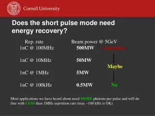
Does the short pulse mode need energy recovery?. Rep. rate Beam power @ 5GeV 1nC @ 100MHz 500MW Absolutely 1nC @ 10MHz 50MW Maybe 1nC @ 1MHz 5MW 1nC @ 100kHz 0.5MW No.

E N D
Does the short pulse mode need energy recovery? Rep. rate Beam power @ 5GeV 1nC @ 100MHz 500MW Absolutely 1nC @ 10MHz 50MW Maybe 1nC @ 1MHz 5MW 1nC @ 100kHz 0.5MW No Most applications we have heard about need MORE photons per pulse and will do fine with LESS than 1MHz repetition rate (max ~100 kHz is OK).
Compressing high ave current (ERL) bunches is a bad idea… • ERL is a single stage compressor must have large energy chirp imposed by the 5 GeV linac increases energy spread by > 10. • Emittance growth due to CSR is penalty one has to pay when bunches are being compressed (easily ~ 10 degradation). • The current will have to be reduced (e.g. 1nC@1MHz) anyway due to problems with resistive heating and wakefields in the arc. • As a result, the high brightness users will abhor the short pulse people.
BC1 BC2 Simultaneous short pulses and generic ERL running 0.5 MW dump 100 A source 80 m long undulator or ID farm 1nC@100kHz 10nC@10kHz … 500 MeV 5 GeV 3rd harmonic linearizer 100 mA source • 10% energy difference between 100 mA and 0.1 mA beams is plenty to separate the beams • Multiple stage bunch compression
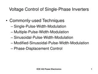
Ig Vb Vc Ib Vg -wave tube h production RF structure ERL Concept: conventional linac e- source
Ig Vb Vc Ib -wave tube 2 Vg 2 RF structure 2 ERL Concept: conventional linac 2 e- source h production
-wave source RF structure ERL Concept: energy recovery linac h production Vc, Vg Ib, dec Ib,acc e- source “same-cell”
-wave source RF structure ERL Concept: energy recovery linac h production Vc, Vg 2 Ib, dec Ib,acc 2 e- source “same-cell”
-wave source RF structure ERL Concept: energy recovery linac h production Vc, Vg 3 Ib, dec Ib,acc 3 extends linac opera- tion to high average currents e- source reduces beam dump energy “same-cell”
Can ERL 0.1 A beam co-exist with 0.1 mA? • currently, each SRF cavity in the main linac is spec’ed for roughly 15 MV voltage, each powered by a klystron of 15 kW • Beam loading due to 100 microAmps beam is only 1.5 kW – 10% of the klystron power • HOM problems in the linac should be addressable as well: low average current; bunch is real short only after BC2 • 0.1 mA bunches can have arbitrary RF phase – can be used to one’s advantage
Performance of 80 m long undulator • Hybrid (vanadium permendur), 2.3 cm period; min gap 5 mm • 109 Photons/pulse/0.1%BW for 1nC bunch
Multiple stage compression • TESLA XFEL: 3 stages; LCLS: 2 stages; BESSY XFEL: 2 stages • Vanilla ERL: 1 stage • Proposed short pulse line in ERL: 2 stages E/E = 10–3 acceleration1 chicane1 acceleration2 chicane2 E/E = 10–4 1st stage 2nd stage . energy . energy . energy . energy rel rel rel rel position position position position
Parametrized 3D FEL simulations applied to the short pulse line specs • 80 m undulator should lase at ~3-4 keV; • Undulator K is large (2.7) 3rd harmonic lasing will happen 3–4 keV: 1012 ph/pulse 10–12 keV: >1010 ph/pulse rep rate: up to 0.1 MHz ERL TN 02-5
Is there an electron source capable of 100 kHz 1nC emittance <1mm-mrad? • not at the moment • but, a source similar to the one currently being built at Cornell has been simulated to be up to the challenge 1nC, 0.7 mm-mrad, 66 A peak current Phys Rev STAB 8, 034202 (2005)
Summary • The proposed short pulse beamline takes advantage of two unique to ERL technologies (hi rep rate photoinjectors, SRF); • Multiple stage compression will enable small energy spread, resulting in saturation length of ~60-80 m with parameters that we believe are achievable; • Simultaneous running of ERL and the short pulse experiments appear feasible; • Will put the accelerator to the frontiers of light source development & performance for many years to come.
Additional thoughts • High bunch charge injector is needed in any event to provide optimal fat bunches for timing exp.; • Only 10% of additional linac is required, i.e. cannot be “make it or break it” from monetary point of view; • Initially, non-XFEL option can be pursued with a long undulator (but not 80 m necessarily) producing 109 photons/pulse @ 0.1 MHz; • Upgrade with 3rd harmonic linearizer linac (if required) and extended undulator will move the ERL accelerator into the new regime of high rep rate XFELs.