Download

1 / 13
130 likes | 256 Vues
This project aims to create an efficient Class-D amplifier for garage bands, delivering over 100W RMS while maintaining high audio quality at a low cost. It utilizes an FPGA for audio processing and has an innovative PWM H-bridge output stage. Key goals include designing user interfaces, integrating digital signal processing, and constructing a protective enclosure for components. This open-source design allows for customization and enhancements, making it suitable for various audio applications. The project will adhere to a defined budget and timeline to ensure successful implementation.

E N D
Class-D Garage Band Amplifier Team: Aaron Danielson, Robert Mann, Randall Newcomb, Scott Russell Sponsor: Nigel Thompson
Overview • The Purpose of the Class-D Garage Band Amplifier • Requirements and Stretch Goals • System Concept • System Block Diagram • Sampling and Bitrate Constraints • Task Breakdown • Budget • Project Schedule
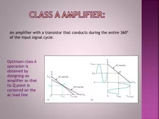
Purpose • Class D Amplifier Power Efficiency • Price Point • Open Source • Customizability
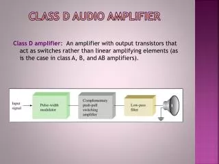
Requirements • An amplifier output will be driven by an FPGA • The output stage will be a PWM H-bridge amplifier • High quality audio • Low cost • High efficiency • The power supply will be efficient and low cost • The amplifier will output more than 100W RMS • … Stretch Goals • An enclosure will be constructed to house the amplifier, FPGA and speaker • A more power amplifier will be implemented
System Concept Images from Google Image
Description of Major Tasks • Design a Top Level Testbench • Contains all the key modules that connect the DSP and PWM. • Implement microprocessor. • Digital Signal Processor • Design 2 filters – one each for bass & treble. • Interface with LCD & rotary dial for user input. • H-Bridge Controller • Design code to control H-bridge IC. • Integrate H-Bridge into FPGA clocking and control. • Amplifier • Design an H-bridge. • Implement and test the amplifier • Speaker Enclosure • Build the box • Shield the box for RF radiation • Design bandpass filters for the selected speaker