Download
1 / 20
200 likes | 366 Vues
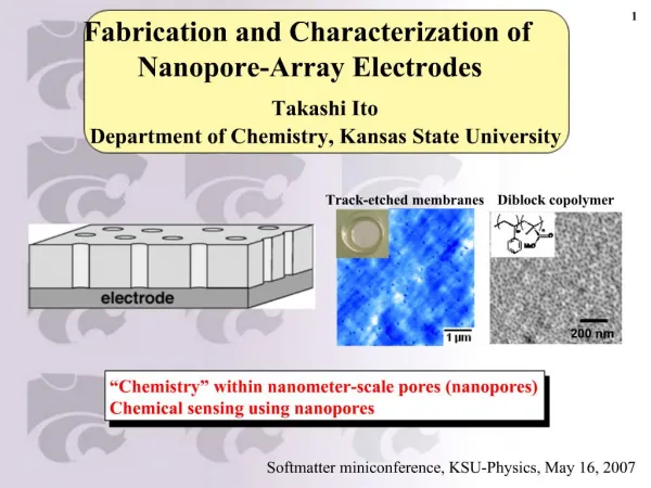
Fabrication of 3D detectors with columnar electrodes of the same doping type. Sabina Ronchin a , Maurizio Boscardin a , Claudio Piemonte a , Alberto Pozza a , Nicola Zorzi a , Gian-Franco Dalla Betta b , Luciano Bosisio c , Giulio Pellegrini d

E N D
Fabrication of 3D detectors with columnar electrodes of the same doping type Sabina Ronchina, Maurizio Boscardina, Claudio Piemontea, Alberto Pozzaa, Nicola Zorzia, Gian-Franco Dalla Bettab, Luciano Bosisioc, Giulio Pellegrinid a ITC-irst, Microsystems Division, via Sommarive, 18 38050 Povo di Trento, Italy b University of Trento, DIT, Trento, Italy c Physics Department, University of Trieste and IN FN, Trieste, Italy dInstituto de Microelectrónica de Barcelona, IMB-CNM-CSIC, 08193 Bellaterra, Barcelona, Spain PSD7
Outline • Introduction • Concept of a Single-Type Column 3D detector • Fabrication of 3D detectors at ITC-irst • Layout of the first batch • Preliminary electrical results • Conclusion PSD7
“Standard” 3D detectors - concept First 3D architecture, proposed by S.I. Parker et al. [1] in 1997: columnar electrodes of both doping types ionizing particle p-columns n-columns wafer surface • Short distance between electrodes: • low full depletion voltage • short collection distance • more radiation tolerant • than planar detectors!! n-type substrate DRAWBACK: Fabrication process rather long and not standard => mass production of 3D devices very critical and very expensive. [1] S.I. Parker, C.J. Kenney, J. Segal, Nucl. Instr. Meth. Phys. Res. A 395 (1997) 328 PSD7
3D-stc detectors proposed at ITC-irst [2] n+ electrodes electrons are swept away by the transversal field 50 m p-type substrate + n electrodes [2] C. Piemonte, M. Boscardin, G.-F. Dalla Betta, S. Ronchin, N. Zorzi, Nucl. Instr. Meth. Phys. Res. A 541 (2005) 441 [3] S. Eränen, T. Virolainen, I. Luusua, J. Kalliopuska, K.Kurvinen, M. Eräluoto, J. Härkönen, K. Leinonen, M. Palviainen and M. Koski, 2004 IEEE Nuclear Science Symposium, Conference Record, paper N28-3, Rome (Italy), October 16-22, 2004 0 V 0V 0V -5 V - - 5V 5V - - - - - - + + potential distribution vertical cross-section between two electrodes - - - - holes drift in the central region and diffuse towards p+ contact + + + + -8 V - - 8V 8V Uniform p+ layer Uniform/grid - - patterned - - -20 V ionizing particle Recently, Semi-3D radiation detectors with p+ columns in n-type substrates were proposed by Eränen et al. [3] PSD7
Simplification of fabrication process n+ electrodes p-type substrate p+ back contact • Single-Type-Column • Etching and column doping • performed only once • Holes not etched all through the wafer No need of support wafer. Bulk contact is provided by a backside uniform p+ implant (single side process) • No hole filling PSD7
Fabrication process (1) • initial oxide • p+-doping of back • Isolation: p-stop or p-spray • masking for deep- RIE process • deep-RIE (CNM,Barcelona-Spain) p-stop oxide p+ doping holes PSD7
Fabrication process (2) • P-diffusion • Oxidation (hole passivation) • Opening contacts • Metal and sintering P- diffused regions metal contacts Hole passivation PSD7
Mask layout “Large” strip-like detectors Small version of strip detectors Planar and 3D test structures “Low density layout” to increase mechanical robustness of the wafer PSD7
Mask Layout-Test structures Standard (planar) test structures 10x10 matrix 3D-Diode Ø hole 10 µm 44 holes GR p-stop 20 µm Ø implant 44 µm Pitch 80 µm PSD7
Mask layout - strip detectors Inner guard ring (bias line) metal p-stop hole • AC and DC coupling • Inter-columns pitch 80-100 m • Two different p-stop layouts • Holes Ø 6 or 10 m Contact opening n+ PSD7
Fabrication run: main characteristics • Substrate: Si High Resistivity,p-type, <100> • FZ (500 m) >5.0 k • Cz (300m) >1.8 k • Surface isolation: • p-stop • p-spray PSD7
SEM micrographs Top-side of a column metal oxide 6 m Portion of a strip detector strip 100 m Column-section PSD7
Electrical Characterization (1) Standard (planar) test structures Different sub-types and thicknesses 2% to 13% variation on single wafer Ileak measured Below full depletion due to Vbreak electrical parameters compatible with standard planar processes DRIE does not endanger device performances PSD7
diode • guard ring • diode • guard ring Electrical Characterization (2)IV measurements 10x10 matrix Ø hole 10 µm Pitch 80 µm Active area ~0.64 mm2 3D-Diode Ileak/column @ 20V 0.33 ±0.24 pA Ileak/column @ 20V 0.67 ±0.12 pA FZ CZ P-stop P-spray P-stop P-spray PSD7
30 25 20 15 Detectors count 10 5 0 0 5 10 15 20 25 30 35 40 45 50 >50 I bias line [nA] Electrical Characterization (3) Strip detectors Current distribution @ 40V of 70 different devices 1detector: 230 columns x 64 strips on 1 cm2 ~ 15000 columns FZ average current per column < 1pA Good process yield PSD7
Conclusions A new type of 3D detector has been conceived which leads to a significant simplification of the process: • hole etching performed only once • no hole filling • no wafer bonding First production is completed: • Good electrical parameters (DRIE does not endanger device performances) • Low leakage currents< 1pA/column and BD ~ 50Vfor p-spray and >100Vfor p-stop in 3Ddiodes • Good performances of strip detectors(Current/hole< 1pA/columnfor93%of detectors) Accurate analysis of CV measurement results is in progress with the aid of TCAD simulations PSD7
TCAD Simulations - static Potential and Electric field along a cut-line from the electrode to the center of the cell Na=1e131/cm3 Na=1e121/cm3 Na=5e121/cm3 Na=5e121/cm3 Na=1e121/cm3 Na=1e131/cm3 To increase the electric field strength one can act on the substrate doping concentration
Lateral depletion-voltage Preliminary “3d-diode”/GR capacitance measurements Weak capacitive coupling at very low voltages (conductive substrate layer between columns) Capacitive coupling between 40 columns (100um=pitch, 150um depth) Vback Cint-Vback ~ 5V lateral full depletion voltage (100µm pitch) Cint
Backplane full-depletion-voltage Preliminary “3d-diode”/back capacitance measurements C-V Lateral depletion contribution to measured capacitance at low voltages Linear 1/C2 vs V region corresponding to the same doping level of planar diodes Saturation capacitance corresponding to a depleted width of ~ 150µm) Column depth ~ 150µm 1/C2-V ~ 40V full depletion voltage (300µm wafer)