Download
1 / 33
920 likes | 2.87k Vues
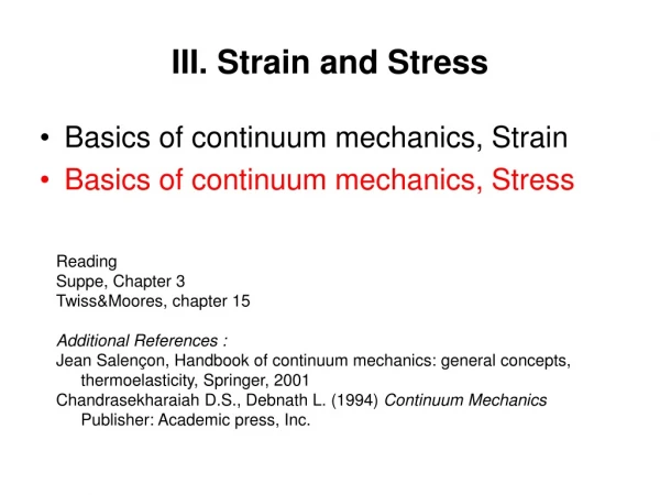
Stress and Strain (3.8-3.12, 3.14). MAE 316 – Strength of Mechanical Components NC State University Department of Mechanical & Aerospace Engineering. Introduction. MAE 316 is a continuation of MAE 314 (solid mechanics) Review topics Beam theory Columns Pressure vessels Principle stresses

E N D
Stress and Strain(3.8-3.12, 3.14) MAE 316 – Strength of Mechanical Components NC State University Department of Mechanical & Aerospace Engineering Stress and Strain
Introduction • MAE 316 is a continuation of MAE 314 (solid mechanics) • Review topics • Beam theory • Columns • Pressure vessels • Principle stresses • New topics • Contact Stress • Press and shrink fits • Fracture mechanics • Fatigue Stress and Strain
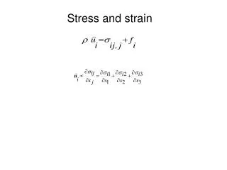
Normal Stress (3.9) • Normal Stress (axial loading) • Sign Convention • σ > 0 Tensile (member is in tension) • σ< 0 Compressive (member is in compression) Stress and Strain
Shear Stress (3.9) • Shear stress (transverse loading) • “Single” shear • “Double” shear average shear stress Stress and Strain
Stress and Strain Review (3.3) • Bearing stress • Bearing stress is a normal stress Single shear case Stress and Strain
Strain (3.8) • Normal strain (axial loading) • Hooke’s Law Where E = Modulus of Elasticity (Young’s modulus) Stress and Strain
Stress and Strain Review (3.12) • Torsion (circular shaft) • Shear strain • Shear stress • Angle of twist T Where G = Shear modulus (Modulus of rigidity)and J = Polar moment of inertia of shaft cross-section Stress and Strain
Thin-Walled Pressure Vessels (3.14) • Thin-walled pressure vessels • Cylindrical • Spherical Circumferential “hoop” stress Longitudinal stress Stress and Strain
Beams in Bending (3.10) • Beams in pure bending • Strain • Stress Where ν = Poisson’s Ratio and ρ = radius of curvature Where I = 2nd moment of inertia of the cross-section Stress and Strain
Beam Shear and Bending (3.10-3.11) • Beams (non-uniform bending) • Shear and bending moment • Shear stress • Design of beams for bending Where Q = 1st moment of the cross-section Stress and Strain
Example Draw the shear and bending-moment diagrams for the beam and loading shown. Stress and Strain
Example Problem An extruded aluminum beam has the cross section shown. Knowing that the vertical shear in the beam is 150 kN, determine the shearing stress a (a) point a, and (b) point b. Shear Stress in Beams
Combined Stress in Beams • In MAE 314, we calculated stress and strain for each type of load separately (axial, centric, transverse, etc.). • When more than one type of load acts on a beam, the combined stress can be found by the superposition of several stress states. Stress and Strain
Combined Stress in Beams • Determine the normal and shearing stress at point K. The radius of the bar is 20 mm. Stress and Strain
2D and 3D Stress(3.6-3.7) MAE 316 – Strength of Mechanical Components NC State University Department of Mechanical & Aerospace Engineering Stress and Strain
Plane (2D) Stress (3.6) • Consider a state of plane stress: σz = τxz = τyz = 0. φ φ φ φ φ φ φ φ Slice cube at an angle φ to the x-axis (new coordinates x’, y’) φ Stress and Strain
Plane (2D) Stress (3.6) • Sum forces in x’ direction and y’ direction and use trig identities to formulate equations for transformed stress. φ φ φ φ φ Stress and Strain
Plane (2D) Stress (3.6) • Plotting a Mohr’s Circle, we can also develop equations for principle stress, maximum shearing stress, and the orientations at which they occur. Stress and Strain
Plane (2D) Strain • Mathematically, the transformation of strain is the same as stress transformation with the following substitutions. Stress and Strain
3D Stress (3.7) • Now, there are three possible principal stresses. • Also, recall the stress tensor can be expressed in matrix form. Stress and Strain
3D Stress (3.7) • We can solve for the principle stresses (σ1, σ2, σ3) using a stress cubic equation. • Where i = 1,2,3 and the three constant I1, I2, and I3 are expressed as follows. Stress and Strain
3D Stress Let nx, ny and nz be the direction cosines of the normal vector to surface ABC with respect to x, y, and z directions respectively. Stress and Strain
3D Stress (3.7) • How do we find the maximum shearing stress? • The most visual method is to observe a 3D Mohr's Circle. • Rank principle stresses largest to smallest: σ1 > σ2 > σ3 σ2 σ3 σ1 Stress and Strain
3D Stress (5.5) • A plane that makes equal angles with the principal planes is called an octahedral plane. Stress and Strain
3D Stress (3.7) • For the stress state shown below, find the principle stresses and maximum shear stress. Stress tensor Stress and Strain
3D Stress (3.7) • Draw Mohr’s Circle for the stress state shown below. Stress tensor Stress and Strain
Curved Beams(3.18) MAE 316 – Strength of Mechanical Components NC State University Department of Mechanical & Aerospace Engineering Stress and Strain
Curved Beams (3.18) • Thus far, we have only analyzed stress in straight beams. • However, there many situations where curved beams are used. Hooks Chain links Curved structural beams Stress and Strain
Curved Beams (3.18) • Assumptions • Pure bending (no shear and axial forces present – will add these later) • Bending occurs in a single plane • The cross-section has at least one axis of symmetry • What does this mean? • σ = -My/Ino longer applies • Neutral axis and axis of symmetry (centroid) are no longer the same • Stress distribution is not linear Stress and Strain
Curved Beams (3.18) Flexure formula for tangential stress: Where M = bending moment about centroidal axis (positive M puts inner surface in tension)y = distance from neutral axis to point of interestA = cross-section areae = distance from centroidal axis to neutral axis rn = radius of neutral axis Stress and Strain
Curved Beams (3.18) • If there is also an axial force present, the flexure formula can be written as follows. • Table 3-4 in the textbook shows rn formulas for several common cross-section shapes. Stress and Strain
Example Plot the distribution of stresses across section A-A of the crane hook shown below. The cross section is rectangular, with b=0.75 in and h =4 in, and the load is F = 5000 lbf. Stress and Strain
Curved Beams (3.18) • Calculate the tangential stress at A and B on the curved hook shown below if the load P = 90 kN. Stress and Strain