Pneumatics and the FIRST Competition
520 likes | 750 Vues
meet Mr. A.R.Power. Pneumatics and the FIRST Competition. It's all about Power. Complete kit Weight equal or lighter than comparable alternatives Simple Review the manual that comes with the pneumatic kit and you’re ready to go. Adjustable Force

Pneumatics and the FIRST Competition
E N D
Presentation Transcript
meet Mr. A.R.Power Pneumatics and the FIRST Competition It's all about Power www.PneumaticFanatics.org
Complete kit Weightequal or lighter than comparable alternatives SimpleReview the manual that comes with the pneumatic kit and you’re ready to go Adjustable Force Different bore cylinders change the available force and By adjusting the applied pressure you can instantly adjust the force Pneumatics in 2006 – Why?The Advantages www.PneumaticFanatics.org
Durableno burned up motors – stall with no damage Strongfrom 9 lbs to 180 lbs – easily adjustable Custom cylinders in just a few days by UPS Last minute additionsadd a valve or a cylinder quickly Pneumatics in 2005 – Why?The Advantages www.PneumaticFanatics.org
Power Transmission & Control • Electrical • Mechanical • Fluid Power • Hydraulics • Oil, Water, other liquids • Pneumatics • Air, other gases Remember Liquid or Gas www.PneumaticFanatics.org
Pneumaticsincluded in the FIRST kit • Compressor and related components • Connectors and tubing • Valves • Actuator (1 is included but up to 3 more can be gotten quickly – check the pneumatic manual) www.PneumaticFanatics.org
Pneumatics Converts Energy – Electrical to Pneumatic Analogous to Generator • Compressor • Connectors • Valves • Directional control • Flow control • Pressure control Analogous to Wires & Terminals Analogous to Relays & Controllers www.PneumaticFanatics.org
Pneumatics Analogous to Motors, Solenoids, etc. • Actuators • Linear – Often called cylinders – can be made to perform complex motions by using mechanical components – this is the type included in your kit • Rotary • Limited Rotation • Self-contained • Rack and pinion or lever • Air Motors or turbines • Clamps www.PneumaticFanatics.org
Review Questions Which is NOT an advantage of pneumatics ? • Forces from 9 to 180 lbs. can be easily achieved • Custom actuators are available quickly • Easy to add extra functionality • Force produced by a cylinder can’t be changed • Simple to apply www.PneumaticFanatics.org
Review Questions Which is NOT an advantage of pneumatics ? • Forces from 9 to 180 lbs. can be easily achieved • Custom Actuators are available quickly • Easy to add extra functionality • Force produced by a cylinder can’t be changed • Simple to apply Correct answer – 4. Force can be changed by changing the bore (diameter) or changing the applied pressure with the regulator www.PneumaticFanatics.org
Review Questions Which statement is correct ? • Your pneumatic kit is complete, although custom cylinders can be gotten quickly. • You need to supply an extension cord to power the compressor from a wall outlet. • Because air is weightless, it will reduce the weight of your robot when pressurized. • The pressure switch is only included to sound an alarm if ambient pressure falls. www.PneumaticFanatics.org
Review Questions Which statement is correct ? • Your pneumatic kit is complete, although custom cylinders can be gotten quickly. • You need to supply an extension cord to power the compressor from a wall outlet. • Because air is weightless, it will reduce the weight of your robot when pressurized. • The pressure switch is only included to sound an alarm if ambient pressure falls. Correct answer – 1. The pneumatic kit is complete. www.PneumaticFanatics.org
The 2005 FIRST Components Overview www.PneumaticFanatics.org
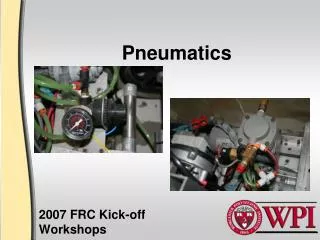
CompressorThomas Industries • Electrically Driven • Additional Components Relief Valve on Compressor Protects compressor Pressure Switch Signals the controller to start or stop the compressor Gauge Reads available pressure Plug Valve Stops air flow Tank(2 included) Stores energy www.PneumaticFanatics.org
The Compressor System Check Valve Flow in one directionbuilt into compressor • Electrically driven • Additional components • Compressor and Relief Valve • Tanks and Pressure Switch • Gauge and Plug Valve • Regulators with gauges www.PneumaticFanatics.org
The Compressor System Additional Components • Tanks & Gauge • Pressure Switch • Relief Valve • Plug Valve Common Pressure In NC NO www.PneumaticFanatics.org
Air Supply Compressed Air is prepared with the use of Filters – Regulators - Lubricators Filter – Regulator w/gauge - Lubricator symbol www.PneumaticFanatics.org
Air Supply But dust, dirt and water areincluded • Ambient air is compressed In industrial applications, contaminants are removed through the use of filters Filter symbol www.PneumaticFanatics.org
Air Supply - Filters • Mesh screens or sintered metal baffles remove dirt • Spinning action forces water and contaminants out of the air stream • Special filter materials remove other entrained contaminants like oil vapors • More water can be removed by air dryers • Chemical • Mechanical www.PneumaticFanatics.org
Air Supply - Regulator • Regulators Control Pressure • Relieving type in the FIRST kit – 2 are included • Non-Relieving type can trap pressure Relieving Regulator and gauge symbol The use of Regulators assures maximum efficiency Set Regulators to about twice minimum pressure necessary to operate the cylinder under load www.PneumaticFanatics.org
About Pressure Safety MUST Compressed Air is like a coiled spring that can be routed to where it is needed • always be considered The bore, stroke and motor horsepower control the pressure from the compressor • The ratio of the uncompressed volume to the compressed volume is the compression ratio • Compressed Air is stored in two tanks • The higher the storage pressure, the more usable energy will be available Relief Valve and Regulator control the working pressure www.PneumaticFanatics.org
Connectors • Hundreds of Variations Available • Size, Type of Connection, Number of Ports • Tubing or Pipe – wrap teflon® tape correctly Tapered Pipe Thread Generally Brass Use Teflon Tape Correctly www.PneumaticFanatics.org
FittingsConnection and Disconnection www.PneumaticFanatics.org
Some Facts about Pneumatics • Pressure – Potential Energy • Lbs per in2 or Force per unit area • Absolute Pressure – 14.7 psia at sea level • Gauge Pressure – measured relative to ambient • Flow • cfm or Volume per unit time • Scfm Voltage Current www.PneumaticFanatics.org
More Facts about Pneumatics • Universal Gas Laws – Boyle’s Law • P1 x V1 = P2 x V2 if Temperature remains constant • That means if you cut the volume in half theabsolute pressure doubles – That’s how the Compressor works 164.1 www.PneumaticFanatics.org
Force Principles • Gauge Pressure works against each square inch of piston surface • The greater the square inch surface of the fluid, the less internal pressure will be developed. www.PneumaticFanatics.org
More Facts about Pneumatics • Universal Gas Laws - Pascal’s Law • Pressure acts at right anglesto the confining vessel – That’s how a cylinder works www.PneumaticFanatics.org
Transmission Principles www.PneumaticFanatics.org
Valves are in Control • Control Pressure • Relief Valves & Regulators • Control Flow • Check Valves (used on compressor) • Flow Controls • Needle Valves www.PneumaticFanatics.org
4-way 5-port ValvesDirectional Control Spring Solenoid www.PneumaticFanatics.org
4-way Valves in your kit • Double Solenoid (detented) • SMC • 2 supplied www.PneumaticFanatics.org
4-way Valves in your kit • Single Solenoid (spring offset) • Festo • 2 supplied www.PneumaticFanatics.org
4-way Valves in your kit • Single SolenoidPoppet (Spring Offset) • Port Sizes: Integrated Fittings: 1/4” O.D. x .040” wall poly tubing (grey tube nuts)*or 6mm x 1mm wall poly tubing (black tube nuts)**Both supplied with valve • Flow: Cv = .20 • Power Consumption: 1.6 Watts • Working Pressure: 20 psi min. (External pilots not available)150 psi max. (Below 1050 F) No vacuum service – Electrical Connectors Included www.PneumaticFanatics.org
4-way Valves in your kitConstruction www.PneumaticFanatics.org
The 4-way valves included in the kit are actually pilot-operated valves. Pilot-operators are 3-waynnp or nc(normally not passing or normally closed) valves built into the main valve. This allows low-power solenoids to use the air pressure to switch the main spool. Solenoids that would actually move the main spool would be large, heavy and consume a lot of power. Valve Symbols www.PneumaticFanatics.org
Compressed Airis routed by the valve to extend or retract the cylinder Animations courtesy of Deyes High Schoolwww.deyes.sefton.sch.uk/technology/AS&Alevel/pneumatic_systems.htm www.PneumaticFanatics.org
ActuatorsMake things move Most Common types of Linear Actuators • Double Acting – Single Ended – Double Ended • Single Acting • Spring Return All contain • Cylinder Barrel • Piston • Rod • Seals • Spring if used www.PneumaticFanatics.org
ActuatorsMake things move Actuators available on order • One linear actuator (cylinder) is included with the kit. This actuator does not include a magnetic piston or reed switches • Three more free actuators can be ordered. One of those may be a rotary actuator. The order form and details are included in the manual. These actuators can be ordered with reed position switches and magnetic pistons. Note the inclusion of reed switches www.PneumaticFanatics.org
ActuatorsConstruction & Operation Basic Construction Operation www.PneumaticFanatics.org
ActuatorsOperation with Flow Controls Typically Flow Controls are mounted between the 4-way valve and the cylinder as close to the cylinder as practical. The check valve permits free flow into the cylinder from the valve and metered flow from the cylinder to exhaust Operation www.PneumaticFanatics.org
ActuatorsDifferential Areas • Force Consideration • Consider the effective area on which the pressure acts • On single ended cylinders there is a differential • Don’t forget friction www.PneumaticFanatics.org
ActuatorsAngles Force T = Cylinder Force x sin A www.PneumaticFanatics.org
ActuatorsAngles www.PneumaticFanatics.org
Actuators - Angles • Example: • Load 15 lbs • Angle 50• • Solution • Step 1 – Force at right angles to support weight = 15 x .643 (cos 50•) = 9.65 lbs = F2 • Step 2 – Effective Cylinder Force at right angles to support weight = 9.65 x arm ratio (17/5) = 32.79 lbs = F1 • Step 3 – Actual Cylinder Force acting at 30• = F1 / sin 30• = 65.59 lbs = F www.PneumaticFanatics.org
Actuator (cylinder) Do’s and Don’ts • You do not have to fully extend a cylinder but you’ll need an external stop. • Avoid side-loading – increases friction and wear • Avoid getting grit or metal shavings on the rod or in the cylinder – causes abrasion and seal damage Weight or force applied at 90° angle to the rod Wear, friction and leakage can occur at the rod seal and at the piston seal www.PneumaticFanatics.org
Actuator (cylinder) do’s and don’ts • Use flow controls for safety • Cylinder Force • Push Force = x cylinder radius2 x Pressure (psig) • Pull Force = Push Force - x rod radius2 x Pressure (psig) • Teams may order additional cylinders (including spares) for rapid delivery using the FAX form is on page 16 of the manual that is included in the kit. ¾”, 1-1/2” or 2” bore are available – see form for available strokes • Avoid leaks – reduces available energy www.PneumaticFanatics.org
Actuators – Mounting Thoughts • Example: Arm to be raised by Cylinder • Determine overall length of retracted cylinder • Draw an arc from the mounting point on arm • Determine overall length of extended cylinder • Draw an arc from the mounting point on arm • Where arcs intersect is the mounting point • Check for intermediate interference www.PneumaticFanatics.org
Calculating Cylinder Dimensions Based on the drawings in the pneumatic manual included with the kit: • Retracted length from pivot pin to clevis hole = • Base Dimension + • Stroke Length + • Locking Nut + • Clevis Dimension • Extended length from pivot pin to clevis hole = • Retracted Length plus Stroke www.PneumaticFanatics.org
1.5” Bore Cylinder • Base Dimension = 4.38 + • Stroke Length = ? + • Locking Nut = .25 + • Clevis Dimension = 1.31 Retracted Length = 4.38 + Stroke + .25 + 1.31 = 5.94 + Stroke Extended Length = 5.94 + (2 x Stroke Length) www.PneumaticFanatics.org
Minimize Leaks (better yet, remove them completely) by careful use of teflon tape and careful assembly of tubing and fittings. Teflon tape should start two threads back and wrap in the direction of the threads. With no movement taking place the compressor should charge the tanks and then shut off. It should not restart until a valve and cylinder is operated Use the Compressor Vibration Isolators. The Compressor is a reciprocating device and will cause sympathetic vibrations throughout your assembly unless they are used. When ordering custom cylinders, use extreme care on the form,both on the address and models ordered Tips & Tricks www.PneumaticFanatics.org
Pressure Switch must be used as inputs to the controller. They cannot handle the amperage of the compressor. The Norgren Regulator should be first with the Monnier unit used after that if needed. Make sure you have adequate pilot pressure (30 psi) for the valves. When using the double solenoid valve, energize only coil one at time. Fittings are not required in the exhaust ports unless the circuit requires them. Always stay clear of cylinders in motion. Until compressed air is being metered, flow controls do little to control speed. Download additional copies of the pneumatic manual from www.PneumaticsFIRST.org Tips & Tricks www.PneumaticFanatics.org