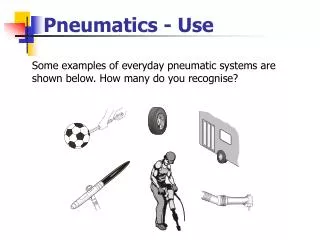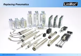
Pneumatics
Pneumatics. Pneumatik. By Clifford Mayhew St Helens College. Basic principles. Pressure Measurement. Pressure Measurement. 1 Bar = 100Kpa = 100KNm -2 = 14.5 PSI. Compression. The pressure inside a closed cylinder will increase as the volume decreases. Gas Law’s.

Pneumatics
E N D
Presentation Transcript
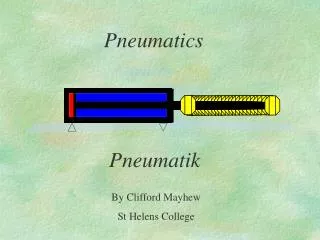
Pneumatics Pneumatik By Clifford Mayhew St Helens College
Pressure Measurement 1 Bar = 100Kpa = 100KNm-2 = 14.5 PSI
Compression The pressure inside a closed cylinder will increase as the volume decreases.
Gas Law’s For a constant temperature, the volume and pressure relationship will obey the law: Pressure x Volume = Constant (Boyle’s Law). This means if volume halves, pressure will double. If volume decreases by a factor of five, pressure will increase by a factor of five etc.
Flow Properties of Air When air flows through a restriction or orifice, there is a drop in pressure. The resulting output pressure is less than the input pressure. When there is no air flow the pressure is the same regardless of the shape of the vessel. This is Pascal’s Law.
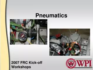
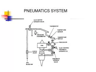
The CompressorKolbenverdichter The compressor uses the gas compression principle to produce high pressure air for pneumatic systems. There are many types of compressor. A common compressor is the piston type shown below.
The ReceiverSpeicher Kessel The receiver collects and stores the air from the compressor.
Air DryerLufttrocknung The compression process produces a lot of water which is forced out of the compressed air. The water must be removed using a dryer.
Air Distribution The pipework from the compressor is run downhill. This also helps to drain water from the system.
Pneumatic Circuits • Pneumatic devices are used for machine control. • Actuating devices can be linear or rotary. • Valves can: • Condition • Regulate • Restrict • Direct • Decide
A Pneumatic Circuit The circuit extends both cylinders in a sequence when the two push button switches are pressed together. The cylinders will stop when the stop push button alone is pressed.
Components • The previous circuit contains a filter regulator lubricator unit (air delivery) which is connected to the mains air supply from the compressor. • Logic valves decide when the operation begins. • Control valves direct the air. • Restrictors control the speed of the cylinders.
Symbols and Components The following slides show some common pneumatic devices and their symbols as used on engineering drawings.
2/2 Way Directional Control Valve2/2 Wegeventil The circuit symbol describes the operation of the valve.
Symbol Operation To see how the symbol works, consider the animation below. Air is initially blocked from passing through the valve. Air is now allowed through the valve to the output.
3/2 Directional Control Valve Normally Closed 3/2 Wegeventil Sperr Ruhestellung A 3/2 valve allows exhaust air to vent to atmosphere in the ‘off’ position.
3/2 Directional Control Valve Normally Open 3/2 Wegeventil Durchflub Ruhestellung
5/2 Directional Control Valve 3/2 Wegeventil A five port valve switches the two output ports from exhaust/pressure to pressure/exhaust.
Inside the 5/2 Valve In this position, pressure is allowed from P to B. Exhaust from A to S. In this position, pressure is allowed from P to A. Exhaust from B to R.
Spool Operation This animation shows the spool (schieber) operating when each pilot is operated.
Cylinder Also known as a linear actuator. This is the component that provides the movement to achieve the machine operation.
5/2 Valve Operation The animation shows the operation of a 5/2 DCV when connected to a differential cylinder. When the device is activated, pressure is switched to the back of the cylinder which now extends. Note that in both positions, air must be able to escape via the exhaust ports. In this position, pressure is connected to the front of the cylinder.
Two Pressure Valve (AND)Zweidruck Ventil An output is achieved when input 1 AND input 2 are activated.
Shuttle Valve (OR)Wechselventil An output is achieved when input 1 OR input 2 are activated.
Pressure Regulator With Relief PortDruckregelventil mit Druckentlastung The output pressure is regulated by the spring pressure.
Inside the Regulator Input pressure is allowed through the normally open valve. Output pressure acts on the diaphragm against the spring. When the output pressure is greater than the spring force the valve closes.
FilterDruckluftfilter The filter is used to remove small particles from the air. If the particles are left in the air they will cause the pneumatic components to stick.
Inside the Filter Air must pass through the filter in order to get to the outlet. Output air is cleaner and drier. Water in the air is allowed to fall into the water bowl. The bowl must be drained regularly.
LubricatorDruckluftoler The lubricator puts a mist of oil into the air. This lubricates the internal components of the pneumatic valves.
Inside the Lubricator Oil is drawn from the bowl due to the pressure drop Air flows through the orifice causing a drop in pressure.
RestrictionsDrossel Blende Restrictions are used to control the air flow to pneumatic devices. The speed of the pneumatic devices will therefore be controlled.
Non Return ValvesRuckschlagventil Check valves are used to allow air in one direction only.
Flow Control With Check ValveDrossel Ruckschlagventil By combining the restrictor and check valve, the air is restricted in one direction only.
Inside the Restrictor and Check Valve Air in this direction closes the check valve and is forced through the restriction. Air in this direction opens the check valve. The restriction is now bypassed.
Valve Actuators Many valves are actuated by some mechanical or electrical method. Below are some common actuation symbols.
Pilot/Spring operation on a 5/2 Valve Before the button is pressed, the spring holds the valve spool in the spring position. When the button is pressed, the button force overcomes the spring force and the valve switches position.