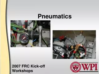
FIRST Pneumatics
FIRST Pneumatics. Team 1425 Wilsonville Robotics. Agenda. Components Basic System Design Applications Tricks of the Trade Resources. Components. Compressor Accumulator Tubing Fittings Release Valve Popoff Valve Regulator and Gauge Pressure Switch with Spike Control Solenoids


FIRST Pneumatics
E N D
Presentation Transcript
FIRST Pneumatics Team 1425 Wilsonville Robotics
Agenda • Components • Basic System Design • Applications • Tricks of the Trade • Resources
Components • Compressor • Accumulator • Tubing • Fittings • Release Valve • Popoff Valve • Regulator and Gauge • Pressure Switch with Spike Control • Solenoids • Actuators
Back Compressor • Used to compress ambient air to do work for you. • Powered by 12 VDC. Eats your battery if you run it continuously. • DC power is connected through a Spike Relay, controlled by robot controller • On/Off control accomplished by monitoring a pressure switch • turns “on” at approximately 95 psi, turns “off” at approximately 115 psi • wired directly to a digital input on robot controller • will need to be programmed by Software Team • Do not put pressure switch in series with 12VDC supply to compressor High pressure air out High pressure air out 12 volts DC Compressor
Back Accumulators • Also known as “air tanks”. • Provides local storage for compressed air, to provide high instantaneous air flow and reduced compressor operation. • Must be placed in circuit immediately after the compressor. • The more tanks you place, the less often your compressor needs to run for each actuation of your pneumatic system. Each tank adds weight. • If your air needs are very low during a round, it is allowable to charge your air tanks between rounds, and eliminate compressor from your robot.
Back Tubing • Flexible and light means of getting air from compressor to other parts. • If you wish to substitute tubing other than what is supplied with kit, be sure that you can prove substitute meets or exceeds working pressure. • Greatest challenge is routing tubing among moving parts so that binding and pinching does not occur – zipties are your friend.
Flow Control Brass Tee 2 tubes into 1 Elbow 2 Tube Teeinto a device Back Fittings • For connecting between devices. • Typically use brass for fitting between devices, or quick connect fittings for connecting tubing to devices. • Lots of choices! Examples are: • Plugs for plugging extra holes • Right angles for making tubing routes compact and out-of-the way • Nipples for connecting between distribution blocks and devices • Use Teflon tape on all male threads, but leave first two threads bare. Otherwise tape will get into your system and clog tiny holes you don’t want clogged.
Back Release Valve • A single valve on the high pressure side • Used to release all air pressure to make system safe to work on
Popoff Valve • An automatic valve on the high pressure side • Prevents high-pressure side from getting too high • Can be mounted directly to the compressor
Back Regulator and Gauges • For setting the working pressure on the low-pressure side of your system, and being able to see what you have set it for. • Regulator must be placed in line immediately after the air tanks. • Maximum downstream pressure is limited to 60 psi by FIRST rules. • Additional secondary regulators (with yellow ring) are supplied if you want to have other circuits at even lower pressure.
Back Pressure Switch • For providing a means for your robot controller to know when to turn the compressor on and off. • Simple electrical switch which “closes” when the pressure is below 95 psi, and “opens” when the pressure is at 115 psi or above. • Must be used, and must be mounted in the high pressure side! • A Spike Relay is used to actually control the DC power to the compressor, not this pressure switch!
Power here and air goes this way Power here and air goes this way Back Solenoids • Also known as “electric valves” • Provides a means for your robot controller to control air flow to a linear actuator or rotary actuator. • Supplied in kit are • double solenoid (two electromagnets) energize one to make ram extend, energize the other to make ram retract, ram will stay put when both are de-energized. • single solenoid (one electromagnet) energize to make ram extend, ram will retract when power is removed (ram won’t stay put) • Spike Relay is used for each electromagnet • Each solenoid has an override button, to actuate without power
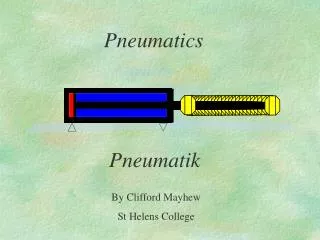
Back Actuators • Come in two types: • Linear (known as Rams) (motion: extends and retracts linearly) • Rotary (motion: rotates a shaft clockwise/counterclockwise a fixed amount) • Provides a variety of uses for lifting, pushing, shifting gears, actuating “paddle” mechanisms • The power available is a function of physical size of the ram and the air pressure. • A 2” diameter bore at 60 psi can create 188 pounds of force • You get different force upon retraction and extension • Not a good choice when precise control over movement or position is needed.
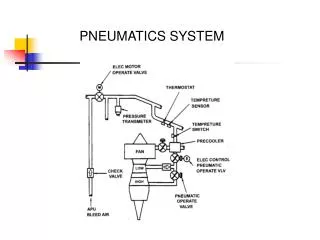
System Design Accumulators Compressor Regulator 60 psi max Spike Pressure Switch 115 psi max Solenoid Gauge Battery Release valve Spike Robot Controller Flow Control
Applications • Controlling a flapper mechanism • Actuating a gear shift mechism • Opening/closing a grabber • Lifting a portion of a robot • Deploying a large device, like a ramp
Tricks of the Trade • Cut the tubing with a sharp knife, squarely • Don’t use side-cutters, you’ll get leaks • The third time you insert tubing in the fitting, it’ll leak (leave tubing long) • Build a manifold to keep a few things together • Pressure switch • High pressure gauge • Release valve • Regulator and distribution
Resources • 2007 Pneumatics Manual from FIRST • http://www2.usfirst.org/2007comp/other/2007%20FRC%20Pneumatics%20Manual.pdf • There are many resources listed in this manual, including manufacturer’s specifications
Parting Words • Remember these three rules • If it is pneumatic, it will leak • It’s easier than it looks • Anything worth doing requires one more trip to the hardware store • Best of luck from Team 1425