Download
1 / 71
720 likes | 866 Vues
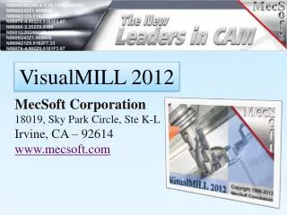
VisualMILL 2012. MecSoft Corporation 18019, Sky Park Circle, Ste K-L Irvine, CA – 92614 www.mecsoft.com. Introducing VisualMILL 2012.

E N D
VisualMILL 2012 MecSoft Corporation 18019, Sky Park Circle, Ste K-L Irvine, CA – 92614 www.mecsoft.com
Introducing VisualMILL 2012 VisualMILL is a 3D solid/surface/STL milling package that includes 2-1/2 Axis, 3 Axis, full rotary 4 axis and 5 axis milling, drilling & free post processors. Powerful – packed with powerful machining strategies. Fast –in computation speed and in programming time. Easy to Use-One of the easiest systems to learn, use and implement. Cost Effective -Priced to provide unsurpassed value for customer investment.
Easy to use Graphical Interface • Native Windows user interface • Windows standards • Vista Compatible • Shaded graphics • Work unambiguously in shaded graphics mode • Browser • User interface innovations to ease programming complexity
File Import/Export Options VisualMILL reads in a variety of file formats reliably and accurately. STL IGES Raw Triangles
VisualMILL Browser • Manage CAM data using the Browser. • Use the browser to • Setup • Create & • Simulate • Machining Operations
Machining Objects Browser The Machining Objects browser allows management of Tools, Machining Regions and Knowledge Bases.
Machining Operation Types Create these types of machining operations in VisualMILL: 2-1/2 Axis - Used for prismatic or extruded parts 3 Axis - Used for complex sculpted shape machining 4 Axis - Machine parts in multiple orientations Hole Making – Drill, tap, bore and reverse bore holes 3+2 Axis - Indexed 3+2 Axis machining for multi-sided parts 5 Axis - Continuous 5 Axis machining complex parts
2-1/2 Axis Machining Power packed 2-1/2 Axis milling methods
2 ½ Axis Facing Machines closed regions as if they were completely enclosing material to be removed.
2 ½ Axis Pocketing Machines closed regions as if they were pockets - completely enclosed by inner and outer regions.
2 ½ Axis Profiling Machines open and closed regions by tracing along one side of their contours.
V-Carve Roughing Method uses a larger cutter to remove material before a V-carve operation is performed.
V-Carving Method is used to machine sharp corners with a V-bit. Especially useful in machining letters and signs.
2 ½ Axis Engraving Engraves text or logos on a finished model. Machines open or closed, 2D or 3D regions by tracing along the contours.
2 ½ Axis Chamfering Method uses a taper bit to create chamfers on sharp corners.
2 ½ Axis Hole Pocketing Method is used to cut large holes using a milling cutter.
2 ½ Axis Thread Milling Method is used to cut threads using a thread mill - internal or external threads, and right or left threads.
2 ½ Slot Milling Method is used to cut slots using a T-Slot cutter.
2 ½ Axis Re-Machining Method uses a smaller tool to remove uncut material left after a previous operation (facing, pocketing, or profiling).*
Form Cutters Create your own cutter profiles to profile custom cross-sectional shapes.*
3 Axis Machining Power, efficiency and control for complex sculpted shape machining.
3 Axis Horizontal Roughing Also known as waterline or constant Z cutting, in which the material is roughed out in horizontal layers.
3 Axis Horizontal Re-Roughing Machine only the material not machined by a previous Horizontal Roughing operation.
3 Axis Plunge Roughing The tool makes a series of overlapping plunges to remove cylindrical plugs of material.
3 Axis Plunge Re-Roughing Method uses plunge motions to machine areas that were not machined by previous operations.
3 Axis Flats Roughing Rough out only flat areas in the part.
3 Axis Parallel Finishing Efficient method of finishing or pre-finishing. The tool moves along a parallel cut pattern, following the contours of the part geometry below.
3 Axis Horizontal Finishing Method is used for pre-finishing or finishing in constant Z levels, typically used when the part has large vertical features.
3 Axis Projection Pocketing Method is used for pre-finishing and finishing of pockets with sculpted bottoms and/or sides.
3 Axis Offset Pocketing Method used to machine pockets wherein the tool moves along the part with a constant 3d step over thereby leaving a constant scallop on the part geometry
3 Axis Offset Profiling Method is used for pre-finishing or finishing wherein the tool simultaneously follows the selected curves and the contours of the part below in constant 3d.* * Available only in the Pro product
3 Axis Pencil Tracing Used either for roughing, re-machining, or cleanup, where the tool is driven along valleys and corners of the part.
3 Axis Valley Re-Machining Machine corners and valleys that were inaccessible in previous finishing operations.
3 Axis Plateau Machining Method machines the tops of flat areas – areas that are within a specified angle from horizontal.
3 Axis Parallel Hill Machining Method machines steep areas. These are areas that are within a specified angle from vertical.
3 Axis Horizontal Hill Machining Method machines in constant Z levels. Machining can be restricted only to areas in the part that are steeper than a user-defined steepness angle.
3 Axis Radial Machining Method is used as a finishing operation for areas that have annular pockets, generating a radial toolpath.
3 Axis Spiral Machining Method is used for finishing areas that have circular or near-circular characteristics, generating a spiral toolpath.
3 Axis Curve Machining Method machines along a curve in isolated areas or shapes.
3 Axis Between 2 Curves Machining Flow-line machining, this method machines between two open or closed curves.
3 Axis Reverse Post Machining • Loads toolpaths from APT CL files and ISO standard G Code files. • Used to : • Project the tool onto part surfaces. • Load an existing toolpath to simulate it in VisualMill.
4 Axis Machining • Complete control for machining parts on a 4 axis rotary table. • Use both indexed and continuous machining methods. • Use Curve based as well as Surface/Solids/Mesh based machining
4 Axis Rotate Table Perform machining by indexing rotary table to any angle to orient the part. Use this to access areas that normally will not be accessible from a simple 3 axis setup.
4 Axis Facing Method is used for clearing out areas on a cylindrical face of a part using curves. Similar to 2 Axis Facing except all machining is performed on the face of a user defined cylinder.
4 Axis Pocketing Method is used for cutting out pockets on a cylindrical face of a part using curves. Similar to 2 Axis Pocketing except all machining is performed on the face of a user defined cylinder.
4 Axis Profiling Method is used for following curves on a cylindrical face of a part using curves. Similar to 2 Axis Profiling except all machining is performed on the face of a user defined cylinder.
4 Axis Engraving Machine text/logos by following the selected regions in continuous 4 Axis mode.
4 Axis Parallel Roughing Rough surfaces/solids/meshes in continuous 4 Axis mode.
4 Axis Parallel Finishing Finish surfaces/solids/meshes in continuous 4 Axis mode.